|
Home • Research • Publication • Glossary • Contacts ______________________________________________
|
||||||||||||||||||||||||||||||||
|
Cryomacroscopy Cryomicroscopy versus cryomacroscopy:
At the
cellular level, visualization of physical events such as crystallization,
devitrification, recrystallization, and fracture formation is commonly done
with the cryomicroscope.
Consistent with efforts to develop cryopreservation techniques for large-size
specimens and organs over the past decade, an urgent need to visualize
physical events in large samples has arisen. For this purpose, cryomacroscopy
technology was invented at the BTTL and kept evolving over the past decade.
The uses of the cryomicroscope and the cryomacroscope are deemed
complementary while their applications for the benefit of cryopreservation
are conceptually different. In cryomicroscopy, representative micro-slices
are exposed to conditions similar to those that would prevail in a
large-scale specimen at selected points, such that a complete picture of the
process can be piecewise-assembled. In cryomacroscopy, the large-scale
specimen is analyzed as a whole in situ. Below is a summary of key
cryomacroscopy prototypes, while selected publications are listed at the
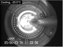
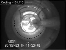
bottom of the page. Cryomacroscope
I has been
developed to study vitrification processes in a sample contained in a 15 mL
vial. In this prototype, a passive cooling mechanism was used by applying
liquid nitrogen-immersed thermal-resistance sleeves of variable thicknesses.
The history of events during the cryogenic protocol was recorded with a HyperHAD monochrome camera on VHS tapes with
visualization capabilities aimed at the scale range of 50 μm to 2 cm.
The thermal history of the same protocol was recorded with a thermocouple,
and analysis of experiments necessitated simultaneous analysis of video tape
and thermal history recordings. Results of Cryomacroscope I studies
demonstrated for the first time that micro
fractures in the glassy state may serve as nucleation sites for
devitrification. Cryomacroscope I was demonstrated as a critical tool for
the observations of rewarming-phase fracturing and rewarming-phase
crystallization (RPC). Results of this study were further used to investigate
fracture formation induced by the contraction of the container wall. Advanced
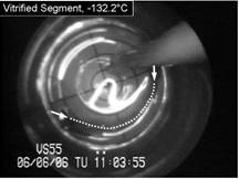
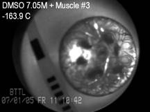
studies with Cryomacroscope I explored the
reasonable boundaries of cryopreservation via vitrification on a rabbit
carotid artery model, with the applications of the CPA cocktail VS55.
These studies were focused on the correlation between crystallization,
fracture formation, and functional recovery of blood vessel specimens. Results
of this investigation demonstrated that the vessel’s mechanical
function was preserved at marginal cooling rates to facilitate vitrification,
with a high contractile response of about 80% relative to the fresh specimen.
These results further indicated localized events of ice crystallization
around the temperature sensor (thermocouple) and at the cannulated ends of
the blood vessel at marginal cooling rates, which correlated well with
post-thawing contractility results.
Cryomacroscope
II has been
developed to study solid-mechanics
effects in thin films. In particular, Cryomacroscope II was designed to
measure the strain to fracture (the relative elongation at the onset of fracturing),
the repeatability of fracturing events, patterns of fracture formation, and
the effects of tissue specimens on stress concentration in a large vitrified
domain. The main differences between Cryomacroscopes I and II are in the
specimen setup and cooling mechanism; while Cryomacroscope I was designed to
mimic a common cryopreservation protocol in a vial, Cryomacroscope II was
designed to investigate specific conditions relevant to solid mechanics
modeling. The thin-film model was chosen as it simplifies the corresponding
solid mechanics analyses, while taking advantage of measurable
substrate-induced forces.
Cryomacroscope III has been designed to
investigate physical events associated with vitrification in the presence of synthetic ice
modulators (SIMs). The main improvement in Cryomacroscope III over
Cryomacroscope I is the cooling mechanism: while Cryomacroscope I used a
tailor-made passive cooling mechanism, Cryomacroscope III was designed to
replace the lid of a commercially available top-loading controlled-rate
cooler. Cryomacroscope III further benefits from an improved high-speed
digital camera and illumination via fiber optics. Cryomacroscopy III results
indicate improved suppression of crystallization with the application of SIMs
and unexpected precipitation of solutes during rewarming. See also movies
on blood vessels vitrification using SIMs.
Cryomacroscope IV has been design for viewing
specimens larger than the field of view of the camera and is also known as
the scanning cryomacroscope. Both Cryomacroscope I and Cryomacroscope
III were designed to visualize physical events with a stationary camera in a
similar arrangement to the cryomicroscope setup, which created an unmet need
for the study of larger size samples—larger than the field of view of
the optical system. Similar to Cryomacroscope III, the new prototype is also
design to be an add-on device to a commercially available controlled-rate
cooler. The development of Cryomacroscope IV includes proprietary software to
control its scanning operation and for post-processing of a single digital
movie for the entire experimental investigation, with all relevant data
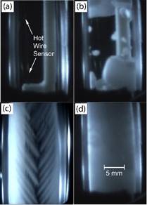
overlaid. Demonstrated
effects in this study included glass formation, various regimes of
crystallization, thermal contraction, and fracture formation. Polarized
light has been further integrated into the scanning cryomacroscope, to
reveal additional effects otherwise not observed with regular light
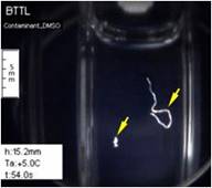
illumination. The following effects have been demonstrated with the polarized
light setup: display of contaminants otherwise unobservable with diffuse
light, observation of ice nuclei, improved contrast in fractured sites, and
visualization of mechanically strained vitrified material, where the strained
material is coded with the visible light spectrum (i.e., photoelastic effects).
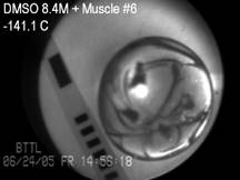
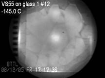
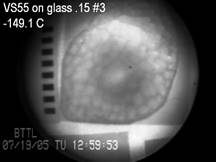
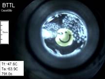
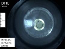
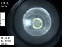
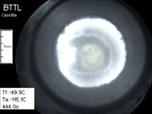
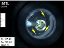
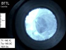
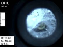
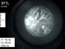
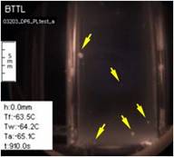
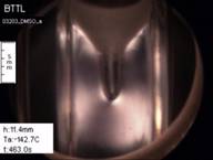
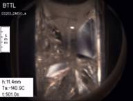
In a recently
study, the scanning cryomacroscope has been demonstrated instrumental in
identifying crystallization events in the investigation of thermal
conductivity of CPAs. Below are selected images from that study, where
visualization is critical for the interpretation of thermal conductivity
measurements.
Selected
publications: •
Solanki,
P.K., Rabin, Y. (2018): Analysis of polarized-light effects in
glass-promoting solutions with applications to cryopreservation and organ
banking, 13(6): e0199155, PubMed, HHS
Public Access, Plos ONE • Ehrlich, L.E., Malen, J.A., Rabin, Y.
(2016): Thermal conductivity of the cryoprotective cocktail DP6 in cryogenic
temperatures, in the presence and absence of synthetic ice modulators,
Cryobiology, 73(2):196-202 PubMed, HHS Public
Access, ScienceDirect • Feig, J.S.G., Solanki, P.K., Eisenberg, D.P., Rabin, Y. (2016):
Polarized light scanning cryomacroscopy, Part II: thermal modeling and
analysis of experimental observations, Cryobiology, 73(2):272-281 PubMed, HHS Public
Access, ScienceDirect • Feig, J.S.G., Eisenberg, D.P., Rabin, Y. (2016): Polarized light
scanning cryomacroscopy, Part I: Experimental apparatus and observations of
vitrification, Crystallization, and Photoelasticity Effects, Cryobiology,
73(2):261-71 PubMed,
HHS Public
Access, ScienceDirect • Feig, J.S.G., Rabin, Y. (2014): The scanning cryomacroscope with
applications to cryopreservation – a device prototype, Cryogenics,
62:118–128 HHS
Public Access, ScienceDirect • Feig, J.S.G., Rabin, Y. (2013): Integration of polarized light into
scanning cryomacroscopy. CRYO2013-the 50th Annual Meeting of the Society for
Cryobiology, N. Bethesda, DC (July 28-31), Cryobiology, 67(3):399-400 ScienceDirect
• Rabin, Y., Taylor, M.J., Feig, J.S.G., Baicu, S., Chen, Z.
(2013): A new cryomacroscope device (Type III) for visualization of physical
events in cryopreservation with applications to vitrification and synthetic
ice modulators, Cryobiology 67(3):264-73 PubMed, HHS Public
Access, ScienceDirect • Rabin, Y., Feig, J.S.G., Williams, A.C., Lin, C.C., Thaokar, C.
(2012): Cryomacroscopy in 3D: a device prototype for the study of
cryopreservation. ASME 2012 Summer Bioengineering Conference - SBC 2012,
Fajardo, Puerto Rico, USA (June 20-23) ASME
Digital Collection, BTTL
Depository • Baicu, S., Taylor, M.J., Chen, Z., Rabin, Y. (2008):
Cryopreservation of carotid artery segments via vitrification subject to
marginal thermal conditions: Correlation of freezing visualization with
functional recovery. Cryobiology, 57(1):1-8 PubMed,
HHS Public
Access, ScienceDirect,
BTTL
Depository • Steif, P.S., Palastro, M.C, Rabin, Y. (2008): Continuum
mechanics analysis of fracture progression in the vitrified cryoprotective
agent DP6. ASME Biomechanical Engineering, 130(2):021006 PubMed, HHS Public
Access, ASME
Digital Collection • Rabin, Y., Steif, P.S., Hess, K.C., Jimenez-Rios, J.L.,
Palastro, M.C. (2006): Fracture formation in vitrified thin films of
cryoprotectants. Cryobiology, 53:75-95 PubMed, HHS Public
Access, ScienceDirect,
BTTL
Depository • Baicu, S., Taylor, M.J., Chen, Z., Rabin, Y. (2006):
Vitrification of carotid artery segments: An integrated study of
thermophysical events and functional recovery towards scale-up for clinical
applications. Cell Preservation Technology, 4(4):236-244 PubMed, HHS Public
Access, BTTL
Depository • Rabin, Y., Steif, P.S. (2006): Solid mechanics aspect of cryobiology, In: Advances in Biopreservation (Baust, J.G., and Baust J.M., Eds.), CRC Taylor & Francis, Chap. 13, pp. 359-382 • Rabin, Y., Taylor, M.J., Walsh, J.R., Baicu, S., Steif, P.S.
(2005): Cryomacroscopy of vitrification, Part I: A prototype and experimental
observations on the cocktails VS55 and DP6. Cell Preservation Technology,
3(3):169-183 PubMed,
HHS Public
Access, BTTL
Depository • Steif, P.S., Palastro, M., Wen, C.R., Baicu, S., Taylor, M.J.,
Rabin, Y. (2005): Cryomacroscopy of vitrification, Part II: Experimental
observations and analysis of fracture formation in vitrified VS55 and DP6.
Cell Preservation Technology, 3(3):184-200 PubMed, HHS Public
Access, BTTL
Depository Acknowledgements:
This
research has been supported, in part, by: • National Heart Lung and Blood Institute (NHLBI) Grant R01HL127618 • National Institute of Biomedical Imaging and Bioengineering
(NIBIB) Grant R21EB011751 •
National
Center for Research Resources (NCRR) Grant R21RR026210 • National
Institute of General Medical Sciences (NIGMS) Grant R21GM103407 •
National Heart Lung and Blood
Institute (NHLBI) Grant R01HL127618 • US Army – Defense Health Program Contract H151-013-0162 |
||||||||||||||||||||||||||||||||
|
______________________________________________ |
||||||||||||||||||||||||||||||||