| Project
1 Part 1
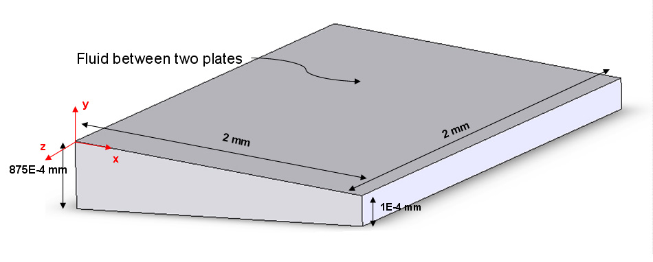
Each student works through the tutorial for
an ANSYS 3-D analysis of the flow of air between 2 plates
with one plate stationary and the other having a velocity
of 19.15 m/sec. The top plate is oriented
at an angle of 2.5 degrees from the bottom (horizontal)
plate.
Other parameters they will use in their analysis
are (see Fig. 1):
r_air
= 1.23 kg/m3
n_air = 1.79 x 10⁻⁵ Ns/m2
Length of plates in the direction of the flow, L = 2.0 x 10⁻³
m (2 mm)
Width of plates normal to the direction of the flow, W = 2.0
x 10-3 m (2 mm)
Separation Distance Between Plates, b2 = 1 x 10⁻⁷ m (100 nm)
b1 = 876 x 10-7 m (87.6 mm) (this
yields an angle of 2.51 degrees)
The students will obtain the following:
A 3-D plot of pressure vs. x and y acting on the stationary
plate
A 3-D plot of Velocity vs. y and z along the center of the
plate (x = 0)
A plot of pressure vs. x where z = -W/2 (-1mm) and y = 0 (on the surface)
A plot of velocity vs. y where x = 0 and z = -W/2 (-1mm)
The total upward normal force on the stationary plate (by
integrating the pressure or by summing up nodal forces).
|