In this section, you will add a control loop around the system to improve the step
response, improve steady-state error, increase bandwidth, and improve disturbance
rejection. The controller will be an inverting summer/gain op-amp circuit as shown below.
The gain will first be selected so as to give one-half the time constant as the open loop
response. The relationship for this circuit is ![]() . Notice the negative on r(t) - this is an
assumed negative. That is, if you give it a positive input you should expect a negative
output.
. Notice the negative on r(t) - this is an
assumed negative. That is, if you give it a positive input you should expect a negative
output.
| Assuming negative feedback, given the open-loop transfer function obtained earlier,
calculate the closed-loop transfer function in terms of the controller gain, Kc, and the
parameters K and | |
| Given the new closed-loop transfer function, calculate the closed-loop time constant, | |
| Calculate the gain, Kc, which results in | |
| Calculate the value of the resistance R2=(KcR1) if R1=560K ohms. This is what you will later set the potentiometer to. |
You will be using a LM324 quad op-amp chip. This chip has, of course, four op-amps - you will only use one in this lab. It requires + and - power, and a GND signal is needed to form the proper circuit. These three power signals will be taken off the terminals from the amplifier. The chip's pin I/O's are shown below.
| Be sure the power is turned off. | |
| Connect the GND terminal of the amplifier to the GND post on the breadboard with a banana cable. | |
| Connect the GND post to the top row of the breadboard with a small jumper wire. | |
| Connect the top row of the breadboard to the second column in from the right with a small jumper. This is the GND column. | |
| Use a long wire to connect the -V terminal of the amplifier to the rightmost column of the breadboard. This is the -V column. | |
| Use a long wire to connect the +V terminal of the amplifier to the first column to the left of the right half section of the breadboard. |
| Insert the chip in the center of the right half of the breadboard so that it straddles the small gap in the middle with the end with the notch facing up (see picture). | |
| Connect the +Vcc pin of the chip to the +V column with a small jumper. | |
| Connect the -Vcc pin of the chip to the -V column with a small jumper. | |
| Connect the + input pin of one of the op-amps (pin 12 in the picture) to the GND column with a small jumper. This sets the zero reference voltage for the summer. |
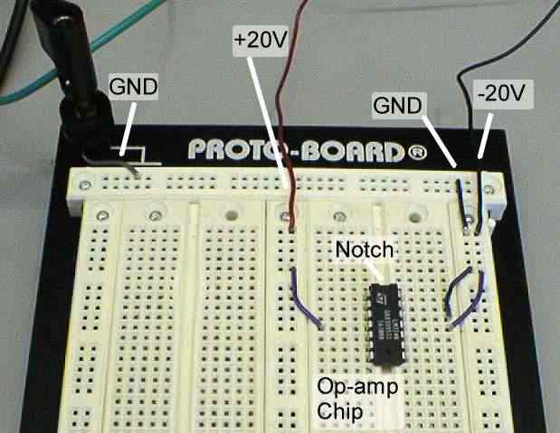 |
| Power Connections for Op-Amp Circuit |
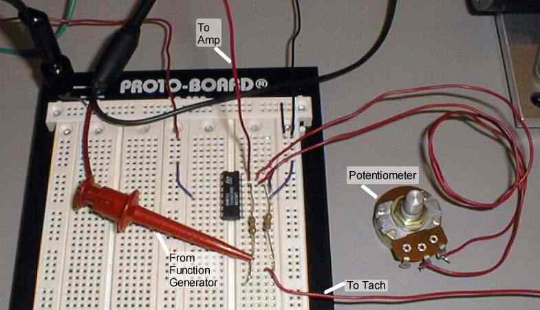
| Use the multimeter to measure the resistance of the potentiometer between the middle lead and one of the end leads. When measuring resistances, be careful not to touch the multimeter leads. | |
| Set the resistance of the pot to the value calculated earlier. | |
| Attach the potentiometer between the output (pin 14) and negative input (pin 13) terminals on the op-amp. Be careful not to change the setting. | |
| Attach two 560K resistors (green-blue-yellow) between the negative input of the op-amp and two different free rows of the breadboard. |
| Detach the red clip from the IN terminal of the amplifier and attach it to the free end of one of the input resistors in the op-amp circuit. This is -r(t), the reference input. | |
| Detach the red clip from the tachometer signal wire and attach it to the corresponding terminal directly on the tach. This will free up the wire. | |
| Attach the tachometer signal wire to the row of breadboard containing the free end of the remaining input resistor. This is the output signal being fed back. | |
| Connect a wire between the output pin of the op-amp (pin 14) and the IN terminal of the amplifier. This is the control signal. |
|
| Controller Circuit Layout |
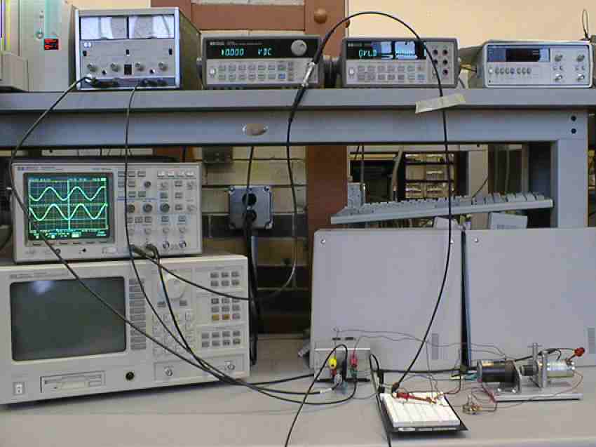
|
| Setup for Closed-Loop |
| Check your connections. It is particularly important that the power be applied to the op-amp in the right direction, and that none of the pins on the chip are shorted to each other. | |
| Set the function generator to a step input of amplitude 5V, offset 5V, and frequency 1Hz. | |
| Set both voltage scales on the oscilloscope to 1V/div. | |
| Set the time scale to 20ms/div, and the time delay to 80ms. | |
| Adjust the vertical position of trace 1 so that the input appears in the top half of the screen. | |
| Turn on the power. If the voltage levels on the power supply do not go up to 20V, then turn it off immediately since something is most likely shorted. | |
| If the motor spins uncontrollably, you are in positive feedback. If this is the case, interchange the two leads from the tachometer. | |
| Adjust the vertical position of trace 2 so it appears in the bottom half of the screen. Trace 2 will most likely be negative when trace 1 is positive. | |
| Adjust the time scale to view the entire step response clearly. | |
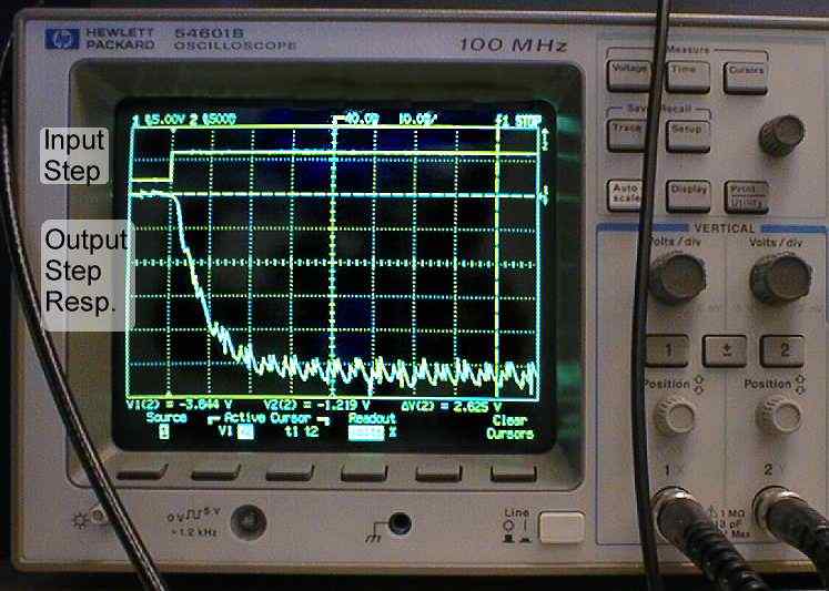
| Use the cursors to measure the output step response amplitude. | |
| Print this screen. | |
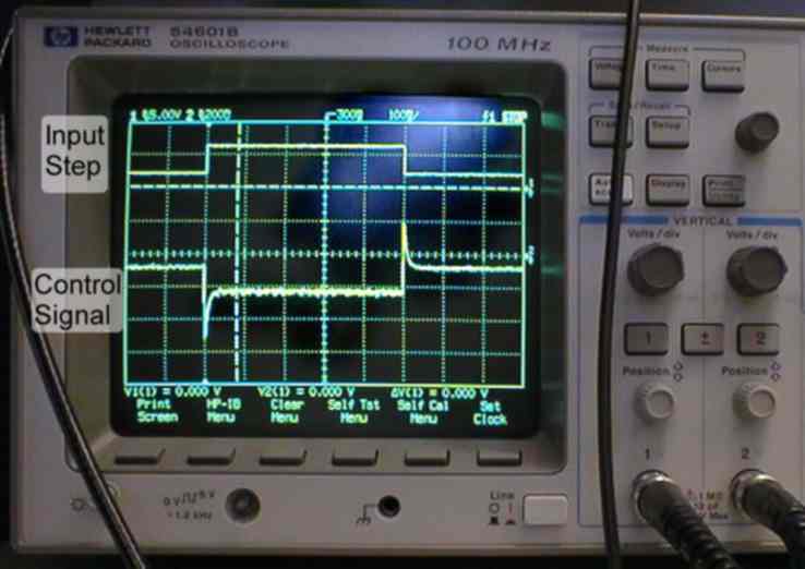
| Move the oscilloscope lead from the tach output to the output of the op-amp. Use an extra wire if necessary. | |
| You are now viewing the control signal to the system. Print this screen and re-attach the oscilloscope clip to the tach output. |
|
|
| Closed-Loop Step Response | Closed-Loop Control Signal |
Follow the same procedure as you did when finding the open-loop bandwidth to find the closed-loop bandwidth.
Follow the same procedure as you did when examining the open-loop disturbance response to examine the closed-loop disturbance response. The shaft should be more difficult to turn now. To compare this with the open-loop, disconnect the motor from the OUT terminal of the amplifier.