The amplifier is powered with +/-20V from the dual power supply. This requires three connections: +20V, GND, and -20V.
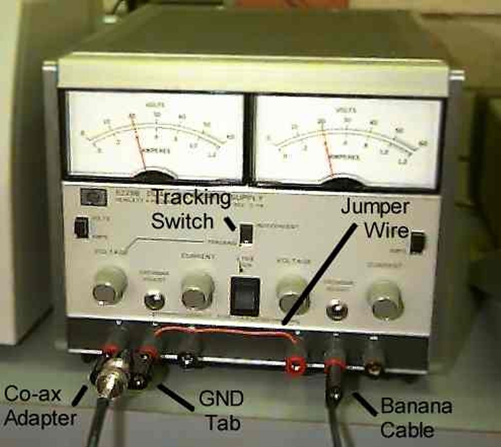
| Set the power supply tracking switch to Independent, and set each side of the power supply to 20V. Turn the supply off! | |
| Connect the negative terminal of the left side of the supply to the positive terminal of the right side with a jumper wire (see picture), creating the GND signal from either of the connected terminals. | |
| Attach a Co-ax/banana adapter to the left side of the supply, with the GND tab to the right. This gives +20V and GND. | |
| Attach a banana cable to the negative terminal of the right side. This gives -20V. |
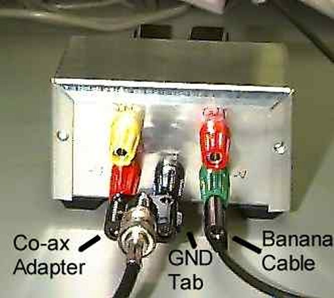
| Attach a Co-ax/banana adapter to the +V and GND terminals of the amplifier with the GND tab to the right. | |
| Connect this to the Co-ax adapter on the power supply with a Co-ax cable. | |
| Plug the banana cable from the -20V on the power supply to the -V terminal of the amplifier. |
| Attach a jumper wire to the GND terminal of the amplifier. All devices must be grounded to the same level. | |
| Attach jumper wires to the IN and OUT terminals of the amplifier. | |
| Attach the black clip of two Co-ax/pigtail clips to the ground wire. | |
| Attach one red clip of the Co-ax/pigtail clips to each of the jumpers on the IN and OUT terminals. |
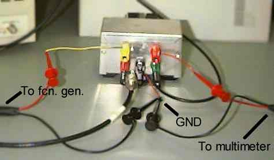
| Attach the IN Co-ax cable from the amplifier to the output of the function generator. | |
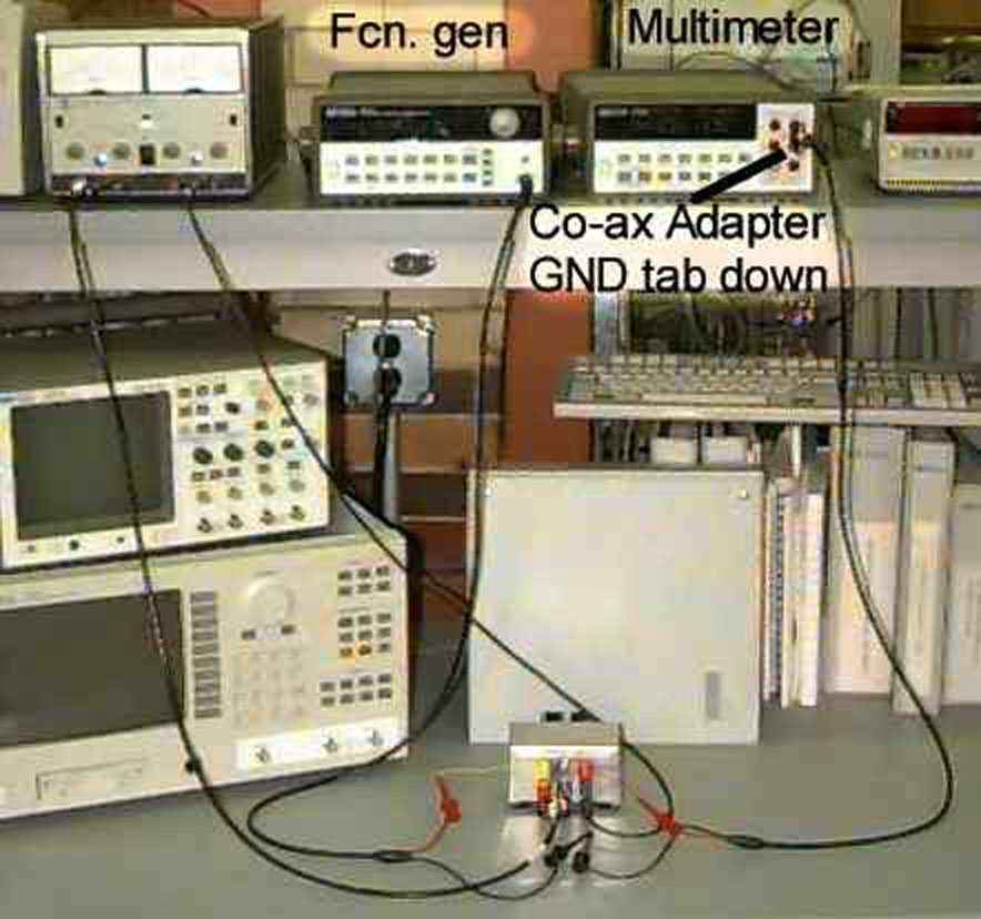
| Attach the OUT Co-ax cable from the amplifier to the multimeter using a Co-ax/banana adapter with the GND tab to the bottom. |
| Hold any of the function shape buttons on the fcn. gen. for several seconds to set it to DC Voltage mode (in order to apply constant voltages to the amplifier). Set the voltage to zero. | |
| Set the multimeter to measure DC Voltage. |
| Check the +20V, GND, and -20V connections to verify they are correct. Do not turn on the power supply unless these connections are correct, or damage to the amplifier will occur (trust me - it WILL happen, including possible explosions). | |
| Turn on the power supply. |
| Verify the calibration of the function generator by setting the DC voltage to 0.1V. Temporarily disconnect the red multimeter lead clip from the output terminal of the amplifier and attach it to the input terminal. The multimeter will most likely read 0.2V. This is due to mis-calibration of the function generator. The multimeter returns the correct voltage. If the multimeter does not read exactly twice the function generator's reading, you will need to measure the input for each data point. | |||||||||||||||||||||||||||||||||||||||||||||||||||||||||
Reconnect the multimeter lead to the amplifier output. Fill out the following table for input voltages and output voltages (use the real input voltage, not the function generator's reading).
| |||||||||||||||||||||||||||||||||||||||||||||||||||||||||