|
Check
your connections. It is particularly important that the power be applied
to the op-amp in the right direction, and that none of the pins on the
chip are shorted to each other. Be careful that none of the resistor
or capacitor leads touch each other. |
|
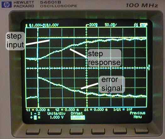
Set
the function generator to a square input of amplitude 1V, offset 1V,
and frequency 1Hz. This will be a square wave alternating between 1V
and 3V. |
|
Set
the trigger to source 1 at a level of 2V with upward slope. |
|
Set
both voltage scales on the oscilloscope to 1V/div. |
|
Set
the time scale to 50ms/div, and the time delay to 200ms. |
|
Adjust
the vertical position of traces 1 and 2 so that the origin of each is
at the origin of the screen. |
|
Set
trace 2 to invert mode. This will get rid of the negative sign
when viewing the signal. |
|
Turn
on the power. If the voltage levels on the power supply do not go up
to 20V, then turn it off immediately since something is most
likely shorted. If this is the case check your connections. |
|
If
the motor spins uncontrollably, you are in positive feedback. If this
is the case, interchange the two leads from the tachometer. |
|
Measure
the error by using the math function on the oscilloscope. To do this,
press the +/- button, turn the math function on, select menu, and choose
the ``-'' function. Set units/div=1V and offset=3V using the knob normally
used for cursors. |
|
Use
the cursors to measure the following:
 |
Steady
State Error |
|
Peak
Time, Tp. |
|
98%
Settling Time, Ts. |
|
%
Overshoot, %OV. |
|
|
Print
this screen. |