In this section, you will add the integral controller. The controller uses of two op-amps from the LM324 quad op-amp chip. The circuit is shown below. Notice that since there are two op-amps, and each one inverts, the negatives cancel. The sign of the feedback term depends on which way the tach wires are connected.
The left op-amp in the circuit is an inverting summer/integrator. The input/output relationship for this portion of the circuit is:
![]()
The right op-amp is an adjustable inverting gain. R3 is a potentiometer which is adjustable between 0 and 100K Ohms. The input/output relationship for this portion of the circuit is:
![]()
These two circuits together provide the non-inverting adjustable integral controller represented by the dotted box in the block diagram.
| Be sure the power is turned off. | |
| Connect the GND terminal of the amplifier to the GND post on the breadboard with a banana cable. | |
| Connect the GND post to the top row of the breadboard with a small jumper wire. | |
| Connect the top row of the breadboard to the second column in from the right with a small jumper. This is the GND column. | |
| Use a long wire to connect the -V terminal of the amplifier to the rightmost column of the breadboard. This is the -V column. | |
| Use a long wire to connect the +V terminal of the amplifier to the first column to the left of the right half section of the breadboard. |
| Insert the chip in the center of the right half of the breadboard so that it straddles the small gap in the middle with the end with the notch facing up (see picture). | |
| Connect the +Vcc pin of the chip to the +V column with a small jumper. | |
| Connect the -Vcc pin of the chip to the -V column with a small jumper. | |
| Connect the + input pins of two of the op-amps (pins 12 and 3 in the picture) to the GND column with a small jumper. This sets the zero reference voltage for the two op-amps. |
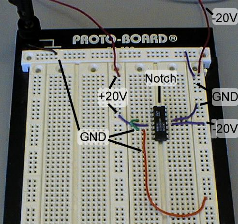 |
| Power Connections for Op-Amp Circuit |
| Connect a | |
| Attach two 560K resistors (green-blue-yellow) between the negative input of the first op-amp (pin 13) and two different free rows of the breadboard. These will be referred to as the input resistors. |
| Use the multimeter to measure the resistance of the potentiometer between the middle lead and one of the end leads. When measuring resistances, be careful not to touch the multimeter leads. | |
| Set the resistance of the pot to the first value calculated earlier. | |
| Attach the potentiometer between the negative input of the second op-amp (pin 2) and a free row of the breadboard. | |
| Attach a 1.5K resistor between the free end of the pot and the output of the first op-amp (pin 14). | |
| Attach a 1.5K resistor between the output and negative input pins of the second op-amp (pins 1 and 2). |
| Detach the red clip from the IN terminal of the amplifier and attach it to the free end of one of the input resistors in the op-amp circuit. This is -r(t), the reference input. | |
| Detach the red clip from the tachometer signal wire. Attach the wire to the free end of the other input resistor. Clip the red clip to the free end of this resistor. This is the feedback signal, -y. | |
| Connect a wire between the output pin of the second op-amp (pin 1) and the IN terminal of the amplifier. This is the control signal, u. |
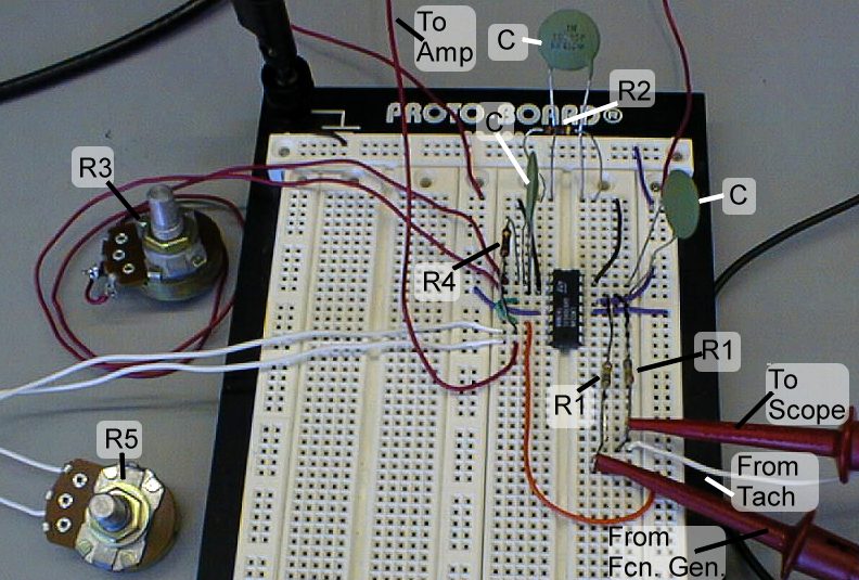
|
| Power Connections for Op-Amp Circuit |
|
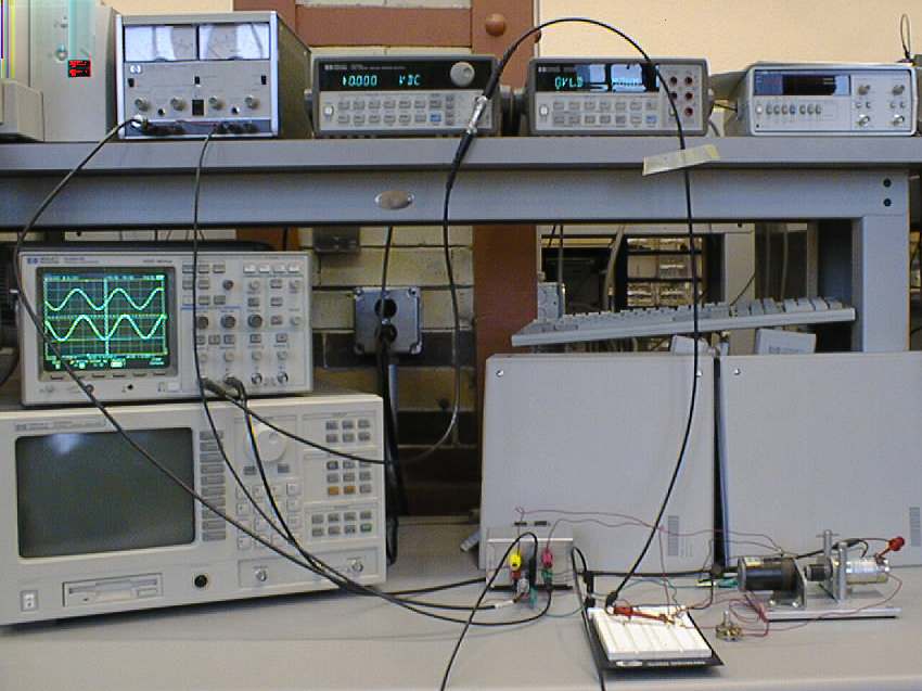
| Setup for Closed-Loop |
Ajay Juneja
Tue Apr 20 13:30:59 EST 1999