The motor, amplifier, and tach together represent the plant in this lab. The open loop TF is
![]()
The plant's gain and time constant can be computed from the open-loop step response, just as was done in Labs 1 and 2 that you performed in Dynamic Systems and Control last semester.
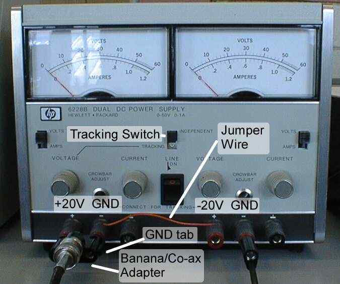
| Set the power supply tracking switch to Independent, and set each side of the power supply to 20V. Turn the supply off! | |
| Connect the negative terminal of the left side of the supply to the positive terminal of the right side with a jumper wire (see picture), creating the GND signal from either of the connected terminals. | |
| Attach a Co-ax/banana adapter to the left side of the supply, with the GND tab to the right. This gives +20V and GND. | |
| Attach a banana cable to the negative terminal of the right side. This gives -20V. | |
| Attach a Co-ax/banana adapter to the +V and GND terminals of the amplifier with the GND tab to the right. | |
| Connect this to the Co-ax adapter on the power supply with a Co-ax cable. | |
| Plug the banana cable from the -20V on the power supply to the -V terminal of the amplifier. |
 |

|
|
| Power Supply | Amplifier |
| Connect the black lead from the motor to the GND terminal of the amplifier, and the red lead to the OUT terminal of the amplifier. These leads should be screwed down to the terminal post. | |
| Attach an alligator clip wire to the GND terminal of the amplifier. | |
| Connect one tachometer lead to the other end of the GND alligator. | |
| Connect a Co-ax/pigtail cable to input 2 of the oscilloscope. Clip the black lead to the GND alligator, and the red lead to the loose lead from the tach. | |
| Attach a short wire to the IN terminal of the amplifier. | |
| Attach a Co-ax T-connector to the output of the function generator. | |
| Connect the function generator output to input 1 of the oscilloscope. | |
| Connect a Co-ax/pigtail cable to the function generator's output. Clip the black lead to the GND alligator, and the red lead to the IN terminal of the amplifier. |

|
| Setup for Open Loop |
| Set function generator to a square wave with amplitude 100mV (This is really 200mVP-P) and frequency 1Hz. | |
| Set the function generator offset to 100mV. (This is really a 200mV offset). This offset is to ensure that the motor is always moving. If the motor is allowed to stop, static friction will affect the response. The step response will occur between a low speed and a high speed, rather than from a stop. | |
| Set oscilloscope voltage scale for input 1 (the input from the fcn. gen.) to 100mV/div. | |
| Set the time scale to 20ms/div. | |
| Set the horizontal delay to 80ms (this moves the step to the left of the screen so that the entire step response can be seen.) | |
| Set the trigger mode to ``normal'' and set the trigger level at about 200mV. If you have trouble triggering, try setting it to ``single'' mode. | |
| Set the vertical position of trace 1 so the step trace appears on the upper half of the screen. | |
| Set the voltage scale for input 2 (the tach output) to 1V/div. | |
| Set the vertical offset so the origin of trace 2 is near the bottom of the screen. |
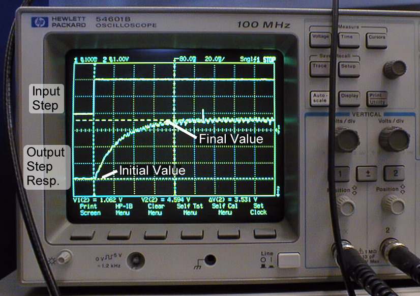
| Turn on power. The motor should spin, and you should get a response similar to that shown below. | |
| Use the cursors to measure the difference in voltage levels between the initial and final values of the output step response. Be sure to use the cursors for trace 2. Record this value. | |
| Print the resulting screen. | |
| In Lab, calculate the K and |
|
| Open Loop Step Response |