
4A. Apply Boundary Conditions
As
stated in the problem description, the plate is constrained from displacement
in the x and y direction at (x=0", y=1") and from displacement in
the y direction at (x=4", y=1")
PREPROCESSOR -> Loads
LOADS -> Define Loads
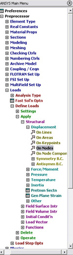
Then select each
node you want to apply displacement on. In this problem, you are asked to
set the displacement along X and Y axis at (0,1) and (4,1) to be zero. In
order to do that, you would have to fix one node at a time.
Let's begin with
point(0,1).
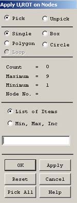
Click on the node(0,1). Then
click OK. Then the window below
will appear.
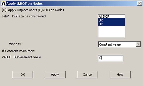
Click on UX
and UY and input a value of
0 in the last box. Click OK.
This figure is
a part of the rectangle after we have fixed point(0,1).

So,
now you can do the second node. Repeat the same procedure EXCEPT that you
set the displacement along Y axis at (4,1) to be zero.
DO
NOT SET UX TO BE ZERO BUT
SET UY TO BE ZERO.
Here
is what the rectangle should look like after we have fixed two points(0,1)
and (4,1),
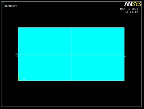
Note : The point on the left side of the plate has two arrows (Constrained
in the x and y directions) and the point on the right side of the plate has
one arrow (Constrained in the y direction only)
REMEMBER
TO SAVE YOUR FILE OFTEN.