Thermal #2: Heat flux
analysis of a composite modular wall
Introduction:
In this
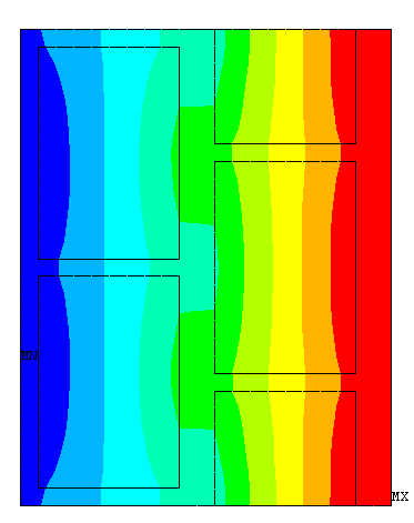
example you will determine the heat flux through the composite modular
wall shown in the figure.
Physical Problem:
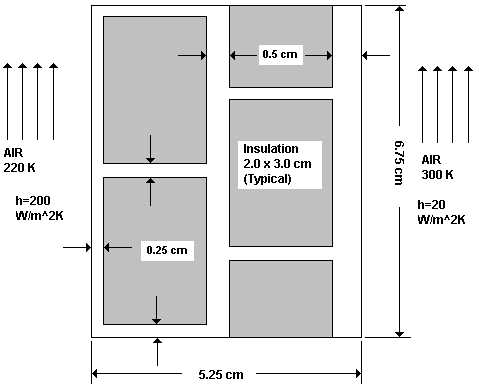
A
composite wall is widely used in cold places to insulate buildings from
the cold outside surroundings. It typically consists of insulating
material packed inside a wall. The insulating material is usually in two
layers and is staggered. In this problem we will model a section of such
a wall and determine the heat flux through the wall. This gives an
estimate of the amount of heat that needs to be supplied to maintain the
room temperature.
Problem Description:
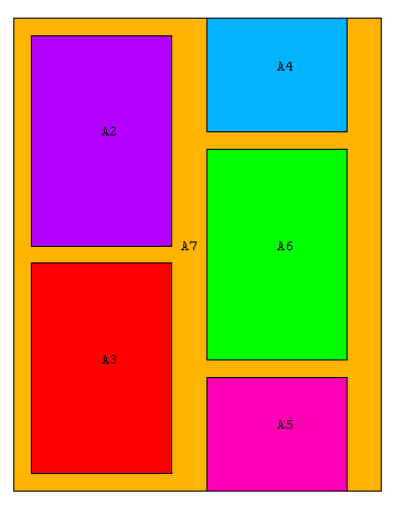
 |
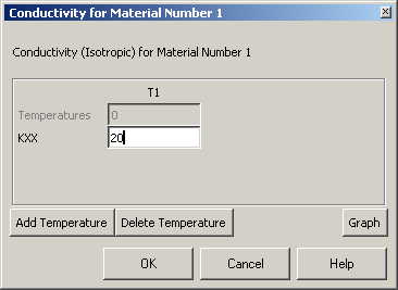
The outer material
of the composite wall is steel with thermal conductivity of 20 W/m K
|
|
The insulating
material has a thermal conductivity of 0.1 W/m K. |
|
Units: Use
S.I. units ONLY |
|
Geometry:
See figure. |
|
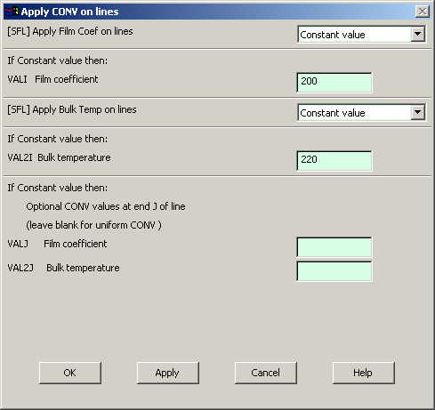
Boundary
Conditions:
The bulk
temperature on the left of the wall is 220K, and the Film
Coefficient is 200 W/m2K. On the right side the bulk
temperature is 300K, and the Film Coefficient is 20 W/m2K. |
|
Objective:
 |
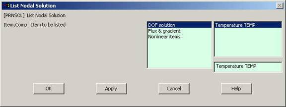
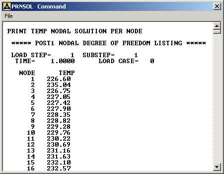
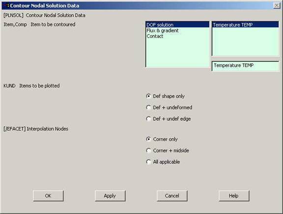
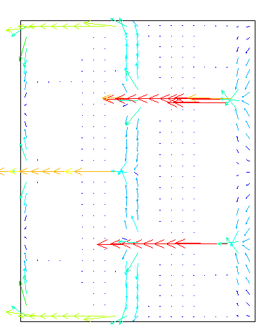
To determine the
heat flux through the given length of the wall. |
|
To plot the
temperature distribution. |
|
To generate the
vector plot of the heat flux. |
|
|
You are required to
hand in print outs for the above. |
|
Figure:
|
|
IMPORTANT:
Convert all
dimensions and forces into SI units. |
STARTING ANSYS
|
Click on ANSYS
6.1 in the programs menu. |
|
Select
Interactive. |
|
The following menu
that comes up. Enter the working directory. All your files will be
stored in this directory. Also enter 64 for Total Workspace and
32 for Database. |
|
Click on Run.
|

MODELING THE STRUCTURE
|
Go to the ANSYS
Utility Menu.
|
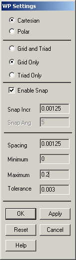
Click
Workplane>WP
Settings.
|
|
The following
window comes up: |
|
|
Check the
Cartesian and Grid Only buttons |
|
Enter the values
shown in the figure above. |