Structural #5: Analysis
of a 3-D Beam structure
Introduction:
In this
example you will learn to use the 3-D Beam element in ANSYS.
Physical Problem: Structural
analysis of the bicycle frame made of hollow aluminum tubing shown in
the figure.
Problem Description:
 |
The cycle frame is
made up of hollow aluminum tubing. These members can be modeled as 3D
Beams. 3D beams experience bending in two directions perpendicular to
the length of the beam. |
|
Units:
Use SI units only |
|
Geometry:
The tubing has an outer diameter of 25mm and a wall thickness of 2mm.
|
|
Material:
Assume the structure is made of aluminum with modulus of elasticity
E=75 GPa.
|
|
Boundary
conditions: The structure is constrained in the X, Y and Z
directions at the bottom three corners. |
|
Loading:
The cycle frame is subject to loading of 600N at the seat (point 2)
and to a loading of 200N at the pedal crank location (point 1).
|
|
Objective:
 |
To determine
deflection at each joint. |
|
To determine the
maximum stress. |
|
Now assume that
your friend needs a ride home and she (he) sits on the back seat
(point 5). Determine the maximum stress now. Remember the extra
loading depends on the weight of your friend. :) |
|
|
You are required to
hand in print outs for the above. |
|
IMPORTANT NOTE:
You can use the stress list to determine the maximum stress but please
do not print this list. The easy way to determine the maximum stress
is to take guesses where the maximum stress should be, Zoom to those
points to get the node numbers or element numbers, then look for SMAX
values at those nodes/elements. |
|
Figure: |
STARTING ANSYS
|
Click on ANSYS
6.1 in the programs menu |
|
Select
Interactive. |
|
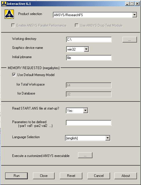
The following menu
that comes up. Enter the working directory. All your files will be
stored in this directory. Also enter 64 for Total Workspace and
32 for Database. |
|
Click on Run.
|
MODELING THE STRUCTURE
|
Go to
ANSYS Utility Menu. Click on
Workplane>Change
Active CS to..>Global Cartesian
|
|
Go to
the ANSYS Main Menu
Preprocessor>Modeling>Create>Keypoints>In
active CS |
|
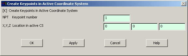
The following
window comes up: |
|
Fill in the
keypoint number (1,2,3...)
and the coordinates. Make sure you get the correct coordinates from
the figure. Create all the 8 keypoints.
Make sure the numbering of your keypoints
matches the numbering of the joints in the figure. |
|
If you cannot see
the complete figure then go to
Utility Menu>PlotCntrls>Pan Zoom Rotate
and zoom out to see the entire figure. |
|
Now create lines
connecting the keypoints |
|
Click
on
Preprocessor>Modeling>Create>Lines>Lines>In Active
Coord |
|
Create lines by
connecting keypoints. Click OK when all
of the lines are made |
|
You can use the
Utility Menu>PlotCtrls>Pan, Zoom, Rotate
window to rotate the model and see its 3D nature. |
MATERIAL PROPERTIES
|
Go to the ANSYS
Main Menu |
|
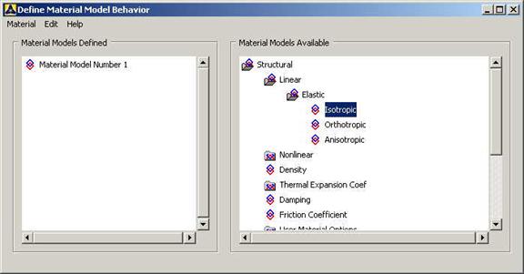
Click
Preprocessor>Material Props>Material Models.
In the window that comes up, select
Structural>Linear>Elastic>Isotropic.
|
|
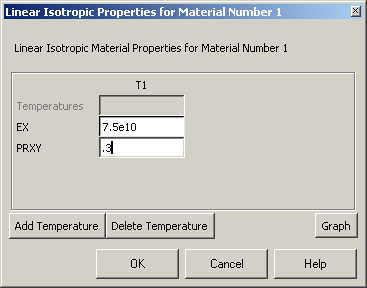
The following
window comes up for Material Model Number 1 |
|
Fill in 7.5e10
for the Young's modulus and 0.3 for minor Poisson's Ratio.
Click OK |
|
Now the material 1
has the properties defined in the above table. We will use this
material for the structure. |
ELEMENT PROPERTIES:
SELECTING ELEMENT TYPE
|
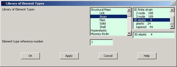
Click
Preprocessor>Element Type>Add/Edit/Delete...
In the 'Element Types' window that opens click on Add... The
following window opens. |
|
Type 1 in
the Element type reference number. |
|
Click on
Structural Beam and select 3D elastic. Click OK. Close the
'Element types' window |
|
So now we have
selected Element type 1 to be a structural Beam 3D elastic element.
The tubings will be modeled as elements of
type 1, i.e. structural 3D Beam element. This finishes the selection
of element type. |
|
Now we need to
define the cross sectional area for this element. |
|
Go to
Preprocessor>Real Constants>Add/Edit/Delete… |
|
In the "Real
Constants" dialog box that comes up click on Add.
|
|
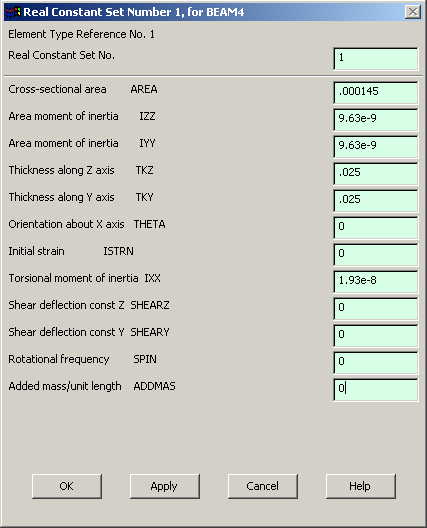
In the "Element
Type for Real Constants" that comes up click OK. The following window
comes up. |
|
Fill in the
relevant values and click on OK. |
|
We have now defined
the cross sectional area, area moment of inertia etc. of the 3D beam
element. |
MESHING:
|
DIVIDING THE FRAME
INTO ELEMENTS:
|
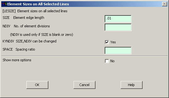
Go to
Preprocessor>Meshing>Size Controls>Manual Size>Lines>All Lines.
In the menu that comes up type 0.01 in the field for 'Element edge
length'. |
|
|
Now we have
defined each element to be of size 10 mm i.e. 0.01 meter |
|
Click on OK.
|
|
Now go to
Preprocessor>Meshing>Mesh>Lines.
|
|
Select all the
lines and click on OK in the "Mesh Lines" dialog box.
|
|
Now each line is
divided into 3D beam elements. |
|
BOUNDARY CONDITIONS AND
CONSTRAINTS:
|
APPLYING BOUNDARY
CONDITIONS
|
The cycle is
constrained in all DOFs at the point 3,4,6,7,8.
|
|
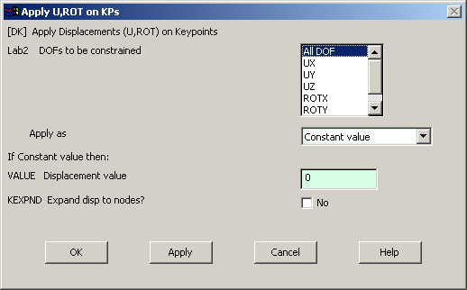
Go
to Main Menu.
Preprocessor>Loads>Define Loads>Apply>Structural>Displacement>On
Keypoints. |
|
Select each
keypoint on which you want to apply
displacement constraints. The following window comes up. |
|
|
Select All DOF
and click OK. |
|
APPLYING FORCES
|
Go to Main Menu
Preprocessor>Loads>Define Loads>Apply>Structural>Forces/Moment>On
Keypoints.
|
|
Select the
keypoint where the force acts. Here we
use keypoints because there are a lot of
nodes and therefore, it is easier to pick
keypoints. |
|
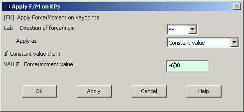
Click on OK in
the "Apply F/M on Keypoints" window. The
following window will appear: |
|
Enter the value
of the force in the Y direction. |
|
Repeat the
procedure to apply the force on the other
keypoint. |
|
|
The model should
look like the one below: |
|
Now the Modeling of
the problem is done. |
SOLUTION:
|
Go to ANSYS
Main Menu>Solution>Analysis Type>New Analysis.
|
|
Select static and
click on OK. |
|
Go to
Solution>Solve>Current LS.
|
|
Wait for ANSYS to
solve the problem. |
|
Click on OK and
close the 'Information' window. |
POST-PROCESSING:
|
Listing the
results: |
|
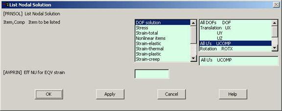
Go to ANSYS Main
Menu
General Postprocessing>List Results>Nodal
Solution.
The following window will come up. |
|
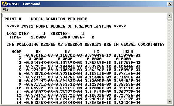
Select DOF
solution and All U's. Click on OK. The nodal displacements
will be listed as follows. Note that the node number may not be the
same node on your project depending on the order in which you picked
your lines to be made. |
|
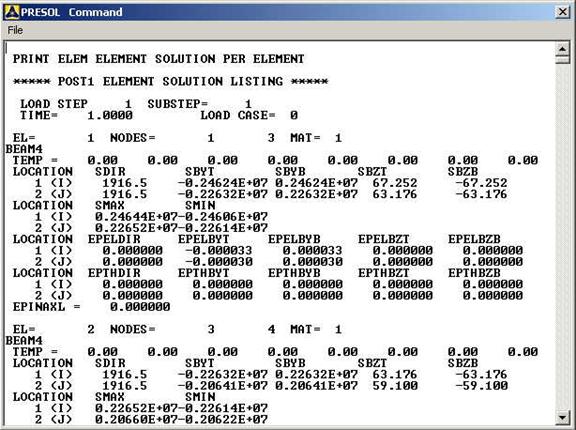
Similarly you can
list the stresses for each element by clicking
General Postprocessing>List
Results>Element Solution.
Now select LineElem Results.
The following table will be listed. |
|
IMPORTANT NOTE:
You can use this list to determine the maximum stress but please do
not print this list. The easy way to determine the maximum stress is
to take guesses where the maximum stress should be, Zoom to those
points to get the node numbers or element numbers, then look for
SMAX values at those nodes/elements. |
MODIFICATIONS:
|
You can also plot
the displacements and stress. |
|
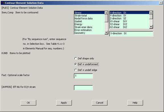
Go to
General Postprocessing>Plot
Results>Contour Plot>Element Solution.
The following window will come up. |
|
Select a stress to
be plotted and click OK. The output will be like this.
|
|