Building a development board is something I have wanted to do for a long time. Like many other robot builders, when I want to just work on a concept or play around with a new sensor, I don't want to have to build a new circuit every time. So I built a development board. It comes complete with a mouthful of features so here I go...
- 5 volt, 2 amp power supply.
- Sockets for all PIC Microcontrollers, with in-circuit programming.
- Sockets for all Basic Stamp microcontrollers, with in-circuit programming.
- Socket for the SX-28 microcontroller, with in-circuit programming.
- 2 x 2 amp motor controllers with directional LEDS. The power can be switched so the motors run on an external battery. This can also be used as a bipolar stepper motor driver.
- Unipolar stepper motor driver with directional LEDS.
- Socket for a parallel LCD in 4-bit mode.
- Socket for a serial LCD.
- 8x8 LED matrix with red and green LEDS.
- 2 x 7-segment common cathode LEDS.
- 2 x 7-segment common anode LEDS with driver chips.
- Peizo speaker.
- Audio amp with connector to attach an external speaker.
- 2 x Potentiometers, with the legs attached to 5 volts and ground.
- DB-9 connector.
- 8 x servo headers.
- 8 x LEDS that can be controlled independently, or through a serial to parallel shift register.
- 8 x buttons that can he read in independently, or through a parallel to serial shift register.
- Solderless breadboard.
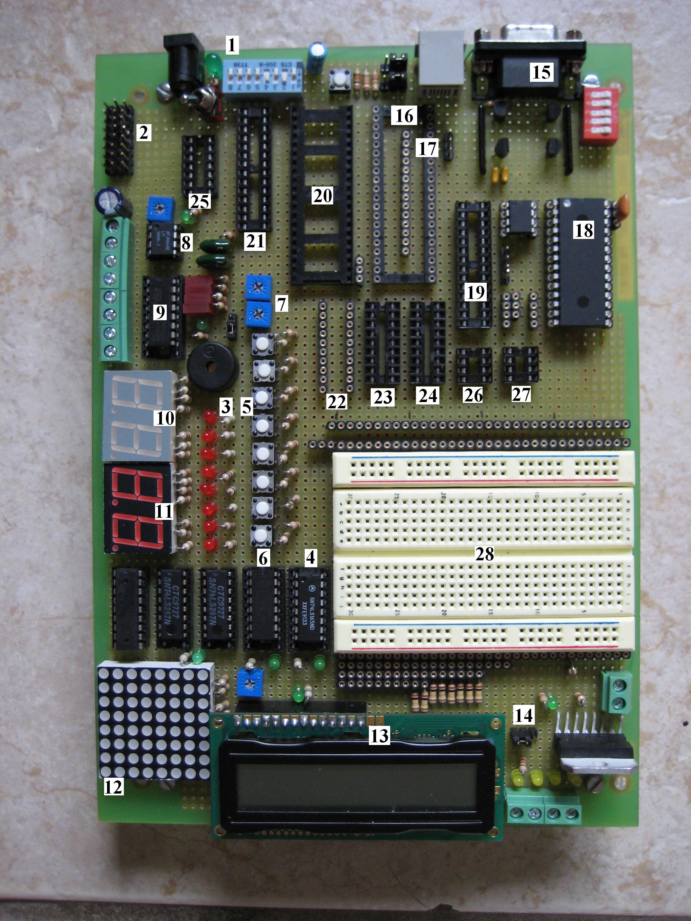
All of the pins for the microcontrollers and the control pins for the devices run to sip headers on the side of the solder-less breadboard. Everything can simply connect to each other using a wire or two.
Next to the power input I placed a set of 8 switches. Each device that requires 5 volts is connected to one of the switches. Now power isn't wasted running a chip that you are not using.
Schematics
1. Power switches for add-onsPin Locations Next to the breadboard
2. 8 x 3-Pin Servo Connectors