Stress Analysis Design Project
Spring 2007
Jason Calaiaro
Rich Pantaleo
Nick Selman
Project Background:
The goal of this project was to
construct a mechanical lifting device. Utilizing only aluminum strips, bolts,
rivets, gears, and the supplied servo, the device needed to reach around and
through a wooden obstacle to lift a 1 pound weight 2 inches in the vertical
direction. The device could weigh a maximum weight of 20 ounces, and it needed
to be capable of performing two lifts of 2 inches in less than 30 seconds.
The Structure:
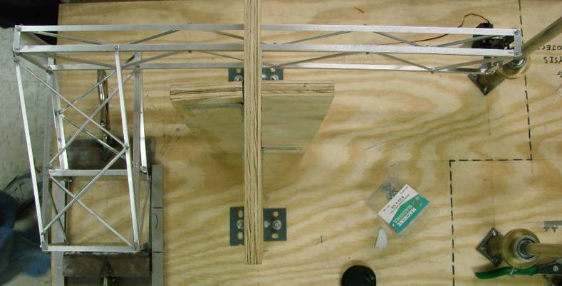
The basic design of our structure
consists of a tall, narrow arm to reach around the playing field obstacle, with
the arm attached to simple but strong angled base. The narrow arm has diagonal
trusses on both sides along its length, which add strength without adding much
weight. The base has a simple design consisting of a simple box with 2
horizontal extensions and 4 diagonal extensions. These extensions are
reinforced with truss members in critical locations that allow very little
deflection of the structure when loaded.
The main “frame” of the structure is
constructed of aluminum strips bent into an “L” shape. The truss members are
made of custom bent aluminum strips in a u channel shape with flattened tab
ends to allow for attachment to the structure. Bolts are used to join pieces
together, though some aluminum rivets were used in the base to allow for clearance
along the side clamping rails. Click
here to view additional pictures of our structure.
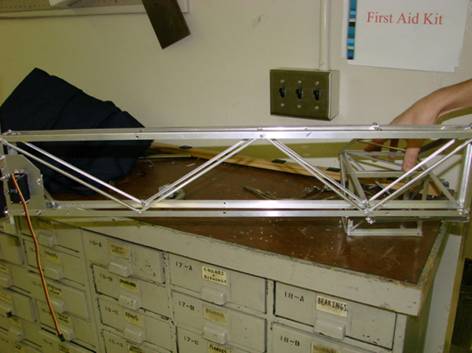
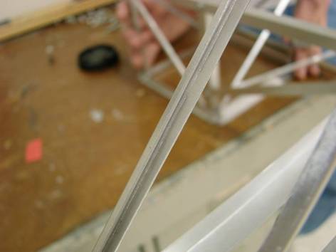
A side view of the
structure showcasing the strategically placed truss members, and a close up
shot a u channel crossmember.
The Mechanism:
The mechanism utilizes a rack and
pinion gear train to lift the weight. A 1.5 inch diameter gear mounted to the
servo meshes with a 0.563 inch diameter gear securely mounted on an axle. A 1
inch pinion gear is also securely mounted on the same axle, and this pinion
gear translates its rotational motion to vertical motion via the rack gear. The
rack gear has a reinforcing spine to prevent it from deflecting when loaded. An
aluminum bracket is bent to the profile of the rack and spine to provide a
means of guiding the rack, keeping its motion purely vertical. Also, the axle
is mounted on delrin bearing blocks to reduce frictional loads.
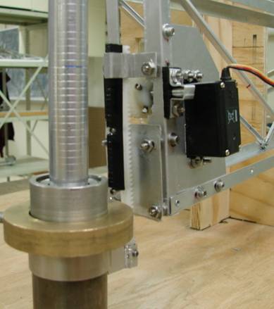
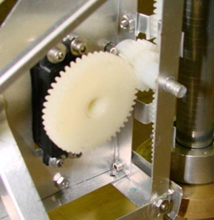
A shot of the completed mechanism
and a close-up view of the gear train, before the delrin bearing blocks were
added.
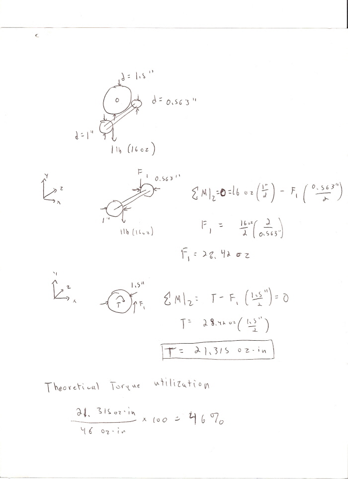
Theoretical Performance
The
theoretical aspects of the servo’s performance are as follows:
Ø
Maximum observed rotation: ~90 degrees
Ø
Maximum theoretical torque output: 46 oz-in
According
to simple statics calculations (summing moments and forces using gear radii as
lever arms) the theoretical amount of torque that the load would exert on the
servo would be 21.315 oz-in. In theory, our mechanism utilizes 46% of the
servo’s maximum torque output. Click here to
view the torque calculations.
With
the gear ratios we used, the theoretical distance over which the rack would
move was observed to be 2.5 inches. In the design competition, our structure
lifted the weight approximately 2.125 inches. Also, our final structure weighed
15.1 ounces.
Solidworks:
Our group took an original
approach to prototyping by first modeling the entire aluminum frame in
Solidworks ®. This was done by dimensioning the already-modeled playing field,
and fitting a basic frame to these dimensions. This basic frame was intended to
“get to the weight” from the base with as little wasted material (and thus,
mass) as possible. It also employed basic Stress Analysis concepts, most
notably the idea of maximizing the moment of inertia of components that
experience large bending moments. This basic frame was then “filled in” with
reinforcing struts and truss components to maximize its rigidity and strength,
and minimize its deflection. This truss system was then re-worked over and over
again, based on the FEA results returned to us by COSMOSworks ® design analyses
on the structure. This allowed us to see where the structure deformed the most,
where we needed to strengthen and reinforce the next iteration, and what
components of the structure were “lazy”, and thus could be removed for
lightening the weight without sacrificing rigidity.
The results were
immediately felt, both in the competition and by our group. Our original frame
never changed, from the first iteration to the final competition, due to the
extremely accurate tolerances measured directly from the playing field and
transferred to our manufacturing practices. Also, the “light but strong”
approach we took to the truss system allowed us to have one of the strongest,
lightest, and best constructed structures in the competition. The entire
structure, sans lifting mechanism and bolts used to secure members, weighed
just 1/2 of the maximum design weight. When loaded, the whole system deflected
a maximum of 1/8”.
Our revolutionary digital
prototyping approach paid immediate, as well as long-lasting, dividends to our
group. The
results speak for themselves.
Unique Aspects of Construction:
Unique to the design of
our mechanism is the rack and pinion gear train. This concept went through several iterations,
beginning with the first rack being machined by hand and meshing with the
26-pitch gears that were provided. We
noticed that we were losing mechanical power to the great amount of friction generated
by the less than perfect meshing, which eventually prompted purchasing properly
meshing gears and rack (since design rules were changed to allow for purchasing
of pre-manufactured gear components.)
What’s different about our design is the fact that we do not use a
counterweight. We wanted the ability to lift the weight solely by the power of
the servo, a daunting challenge we were certainly up for.
Also, we had drafted
extensive plans for a ratchet mechanism that would have given us a theoretical lift
of 12 inches (the entire length of our untrimmed rack.) This would have been accomplished by directly
integrating a ratchet onto a gear that was also secured to the main axle. This would allow the mechanism to be driven
in one direction, but slip over in the other.
Additionally, we would have integrated a secondary ratchet on the axle
of the pinion gear driving the rack.
This secondary rack would “lock” the load in place, ensuring that it
would not fall down when we made the “slipping” pass to lift again. This design, had it been allowed, would have
achieved an all-time lift record, but due a certain infraction with the rules,
it was disallowed.
With a rack design, friction is
the enemy. WD-40 greatly improved the efficiency of our design.

Content
on this website is the property of Jason Calaiaro, Richard Pantaleo, and
Nicolas Selman, founders of RNJ Solutions. RNJ … we build it better.