15-462, Computer Graphics Final Project - ScottyVR
Vivek Sridhar - Cyrus Tabrizi
Note: Code has been copied to Cyrus Tabrizi (ctabrizi) 's 15-462 folder under the directory called "/final"
For our computer graphics final project, we added virtual reality support to Scotty3D! We modified the application user interface to support VR-related functionality, particularly a stereo camera, and added a stereo rendering mode that renders two images side-by-side with distortion such that they can be viewed in a VR headset such as a Google Cardboard. Listed below are some details of our implementation and how to use ScottyVR.
Added raytracing support for a stereo camera. There is a flag in the Camera class that designates a camera as stereo, which changes how the raytracer behaves with respect to rendering. Mono view rendering work as usual. The way that stereo works is by taking the left half of pixels and mapping them to a full square representing the left eye and taking the right half of pixels and mapping them to a full square representing the right eye. There are parameters describing how far apart the centers of these two views should be from each other as well as the space between the camera origins in the world space. The current implementation of this is somewhat hacky with respect to "software design principles" but gets the job done well.
We added support for multiple mono and stereo cameras in ScottyVR, up to some arbitrary N. Currently, there are 3 cameras. The first camera defaults to stereo, the remaining default to mono.
Added a hotkey (';') to switch between the different cameras. Repeatedly pressing this hotkey iterates through the cameras in numerical order (and then wraps around).
A hotkey ('j' or 'J') to switch the type of the current camera from mono to stereo (it will keep toggling). This only matters for raytracing purposes.
Added an openGL model for each camera. Every camera will show up in the views of all cameras except the currently enabled one. This allows you to view the positions of the other cameras in the scene. This only affects non-production modes (i.e. the cameras will not show up in your final render).
Implemented ray-based barrel distortion with two tuning parameters (k0 and k1). This is different from using a texture map or otherwise distorting an already computed image. The benefits of this include maintaining resolution, instead of losing resolution in the most distorted regions. The rays that are sent into the scene are redirected so that resulting image becomes undistorted when viewed through the lens! The way this was done was by computing the radius about the z axis (r = sqrt(x^2 + y^2)) and then rescaling the x,y to meet have a new radius (r_new = r_old*(k0 + k1*r_old^2)).
Implemented a naive form of foveated rendering. Where a fixed number of rays were traced for a given pixel in a mono-view camera (the variable ns_aa), the form of foveated rendering that we implemented involved varying the number of rays depending on the position of the pixel being tested (based on the magical formula below, which was derived in matlab because it looked appropriate: u = ((((1-pow((r/(sqrt(0.5))/3.0),0.175))-0.175093)*100.0)/57.0), where r is the radius represented by the x,y coordinates with respect to the center and u is value from 0 to 1, where 1 will map to the highest ns_aa). The intended priority is to focus the computation time and resources around the points at the center of the view. (In practice, we found the equation to prioritize the center far too excessively.) In this implementation of foveated rendering, higher quality at the center means sampling the most rays around the center. This results in a radial distribution of sampling rates. When ns_aa is entered at the command line, this will adjust the maximum value in the distribution (which will be used at the center) and the rest will scale such that the minimum number of rays is 1. When the camera is a mono camera and not a stereo camera, the radial distribution will not be used, and ns_aa will affect all pixels uniformly, as expected.
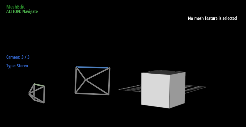
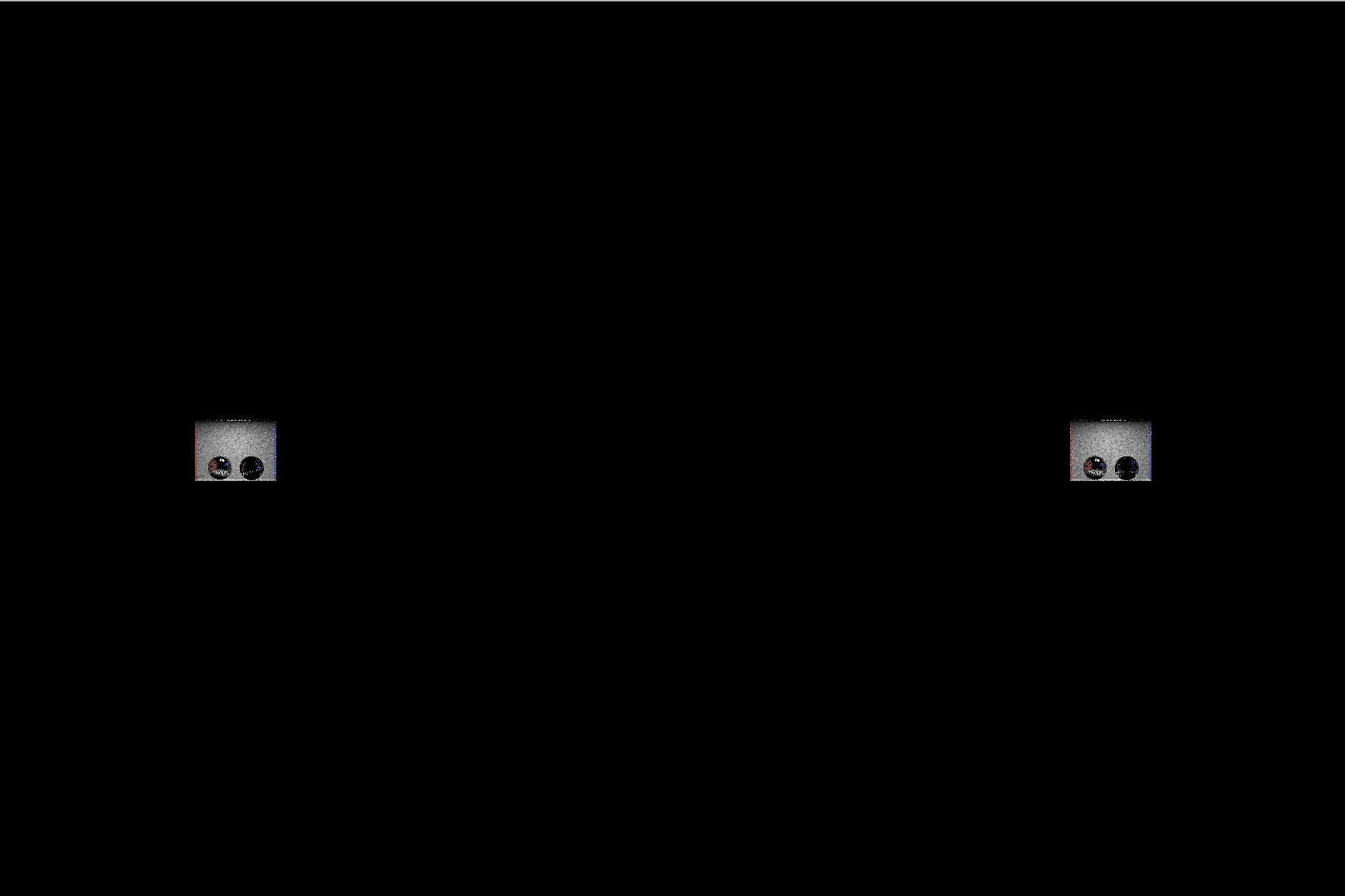
Added text to the UI to display which camera is in use, and what type the camera is. This can be seen on the left
Additional Notes
ScottyVR can be used normally for most normal editing tasks. However, if you wish to render a stereo camera and view the result in a headset like Google Cardboard, we found that the best result to view renders in VR (rather than manually transferring the photos to a phone) is to use a remote desktop app (VNC viewer, for example) on your phone, and simply maximize the ScottyVR render window on the computer. This should help get a preview of what renders will look like when, for example, a full video is rendered and transferred to a mobile device. It's also really convenient. It's important to note that depending on the size and proportions of your monitor and phone, the parameters used for stereo may need to be readjusted. This is because the distance between the center of the lenses on the cardboard remains fixed globally, but the centers of the views in the image may change depending on how they were captured and displayed.
In the project proposal, we stated that we will modify the viewer to display two camera views side by side. However, we determined that having two stereo views slightly offset from each other in normal operation of Scotty3D would be extremely confusing to the user. Therefore, we decided to only show a single view of the stereo camera in regular use, opting to display the full stereo view when a render is requested from a stereo camera.
Currently, there are no stereo-specific optimizations being performed as each view is rendered completely separately. One could imagine a scenario where the closeness of the camera origins to each other could be used to improve ray-geometry intersection performance in the same way one might do so when sampling multiple rays per pixel (which has not been implemented either).
We have rendered a stereo video and put it on YouTube (embedded below). It can be viewed simply by watching it fullscreen on a Google Cardboard. Reminder, there is obviously no head tracking! Also, other VR headsets may not have the same physical properties of the Cardboard and may not be compatible.
Pictures and Video
Above: short video rendered in stereo using ScottyVR
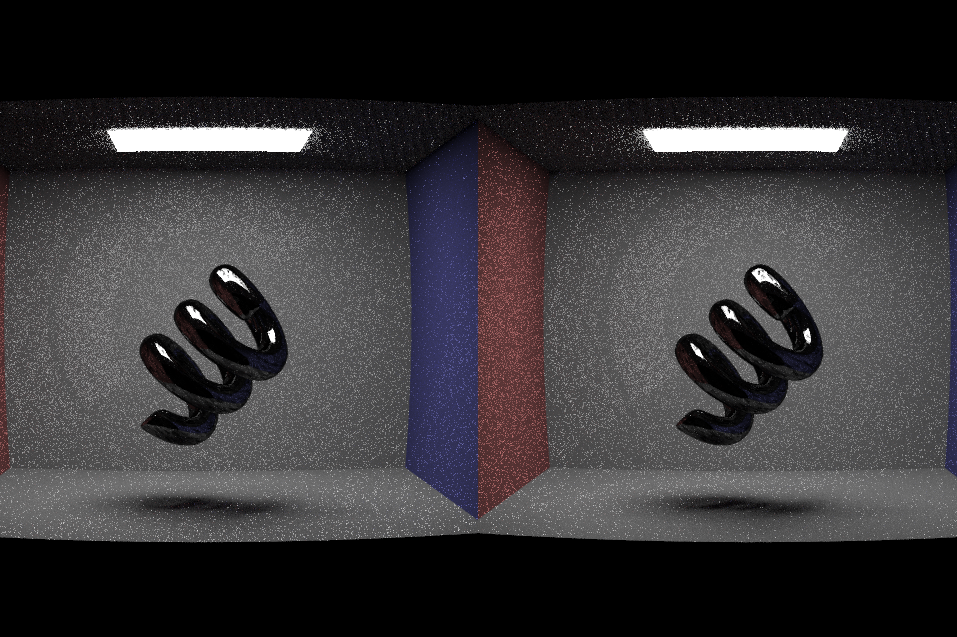
Above: Example output used on CBcoil.dae
Above: Shown above are the labels showing which camera is currently enabled as well as the OpenGL wireframe around the other cameras.
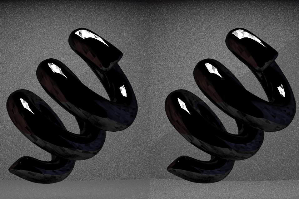
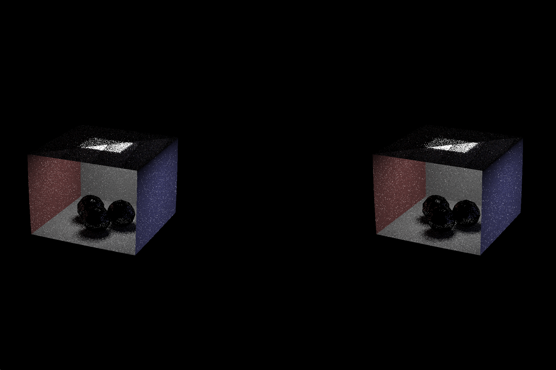
Above: The views of the left and right eye are separated as a percentage of the screen. Here, the separation was left blank.
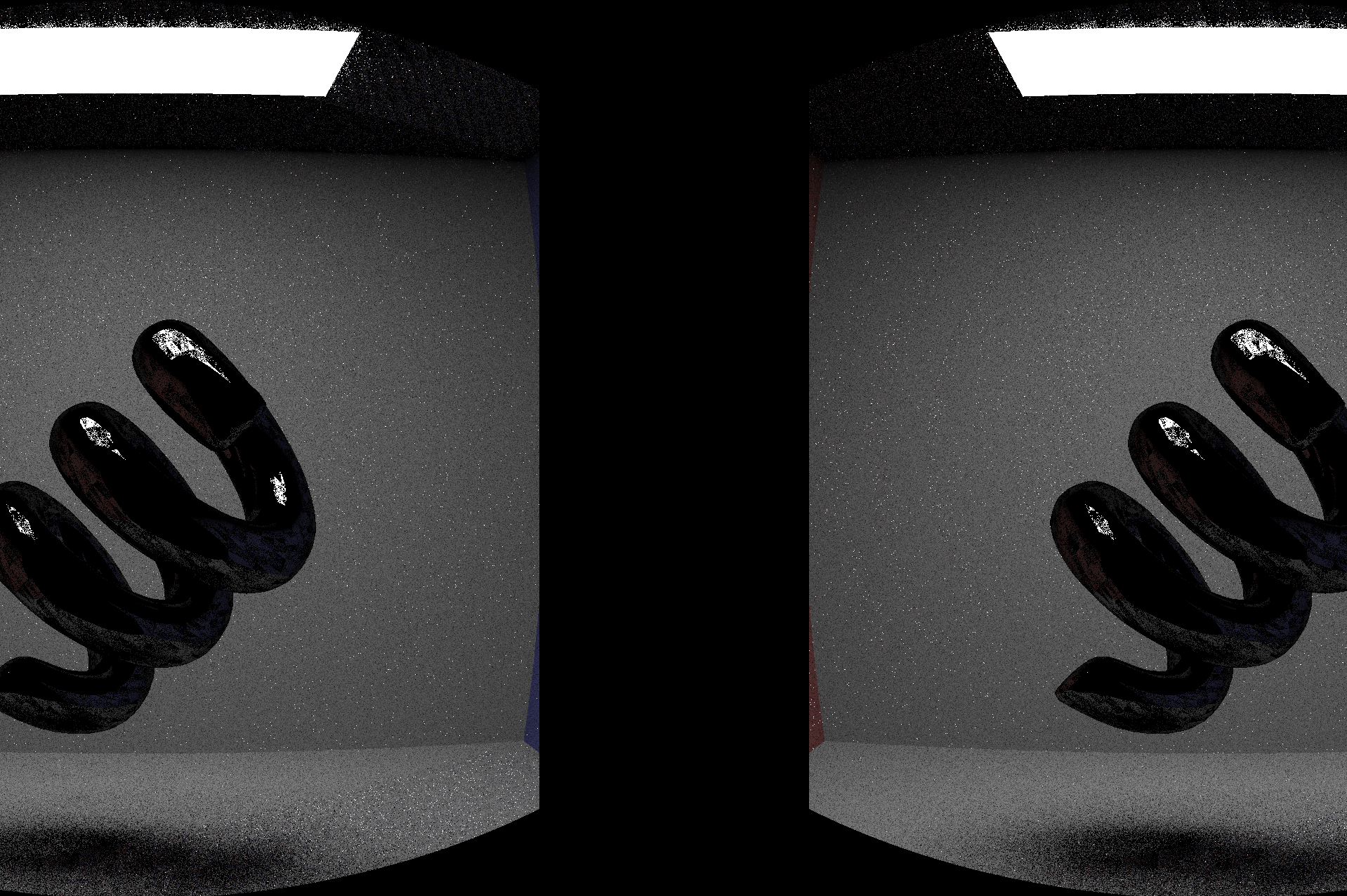
Above: An attempt at calibrating the eye separation parameters by positioning the scene far away from the camera!
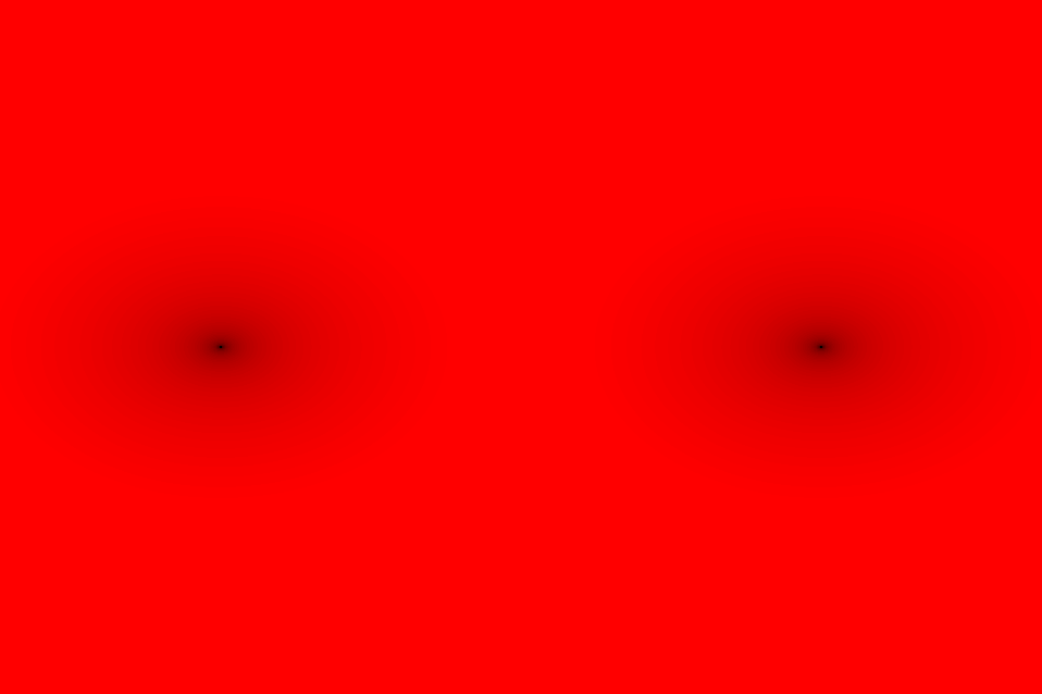
Above: Replaced the pixel value with the red channel proportional to the number of rays sampled per pixel. It's highest around the black points.
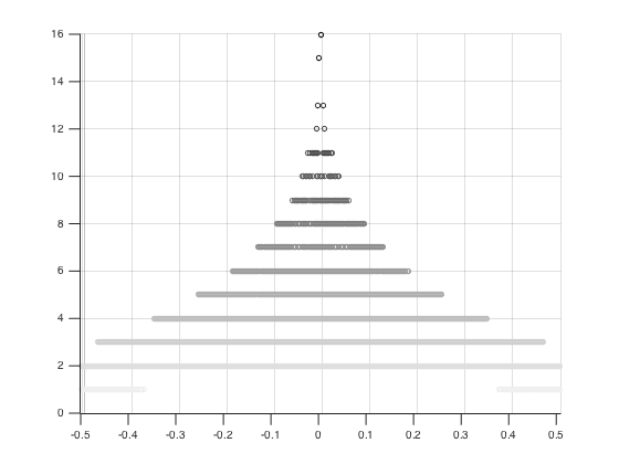
Above: distribution used for foveated rendering! The z-axis represents the number of sample rays traced and averaged for a given pixel. In this case, the maximum ns_aa was 16. The minimum is 1. This is probably too steep of a dropoff but can be changed easily by formula
For our project, we propose modifying the raytracer in Scotty3D to support generating videos for VR! The goal is to be able to set up a scene (animated or not) and then animate the camera to move around the scene. Then we'll output images like we did for Assignment 4, save the images as a video, load the video on a smartphone and view it with a Google Cardboard headset.
This will mostly involve changes to the code done in Assignments 3 and 4 as specified below:
Add a stereo camera class and put one in the scene. This stereo camera will contain two of the existing cameras as objects but allows us to specify the position and orientation of each of those camera with respect to the center of the pair instead of trying to control them independently with respect to the world frame.
Modify the viewer to display two camera views side by side. First, we'll test this by displaying the same camera view in both images. Then we'll use the stereo camera feed to generate unique left and right images
Modify the stereo camera class to allow the two cameras to focus at different distances. Focusing at infinity leaves the cameras directed parallel to each other. Focusing at zero leaves them directed at each other.
Next, we will add lens distortion to the cameras, so the video will appear normal in a VR viewer. This will involve using a camera matrix. More on this here and here and here.
Foveated rendering allows for more resolution where the eyes are directed. Examples are linked to below. This is not the same as controlling the samples per pixel. It means changing the pixel density (or, equivalently, increasing the number of pixels on the screen and then setting nearby pixels to the same value to "cluster" them, effectively blurring some and leaving others with the original resolution).
Finally, we will add the ability to move and animate cameras and their properties (like the focus distance). This will involve adding support for multiple cameras in a scene, as well as switching between them. For example, if we want to view the path that the stereo camera will take, we need to be able to see the path from somewhere else in the scene. This means adding keyboard controls and possibly making some additions to GUI. In addition, we will add the ability for cameras to be moved around like other geometric objects, including animating them using spline interpolation.
If there's time, we might be able to eliminate some approximately redundant computations by approximating the cameras as being in the same pose for some computations and separately for others (need to be careful not to eliminate the stereo effect).