|
We will model the
bracket as a solid 8 node plane stress element. By a plane stress
element we are assuming that there are no stresses in the thickness
direction of the bracket. |
|
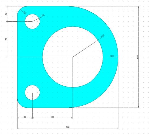
Geometry:
The thickness of the bracket is 3.125 mm |
|
Material:
Assume the structure is made of steel with modulus of elasticity E=200
GPa. |
|
Boundary conditions:
The bracket is fixed at the screw holes. |
|
Loading:
The bracket is loaded at one point in the center of the large hole.
The load is 2000 N. |
|
Objective:
 |
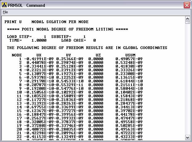
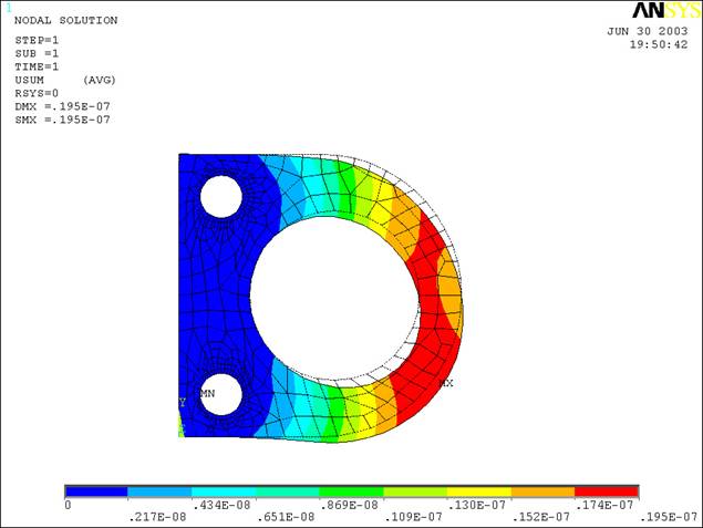
Plot deformed
shape |
|
Determine the
principal stress and the von Mises stress. (Use the stress plots to
determine these) |
|
Remodel the
bracket without the fillet at the corner, and see how principal
stress and von Mises stress change. |
|
|
You are required to
hand in print outs for the above. |
|
Figure: |
IMPORTANT:
Convert
all dimensions and forces into SI units
·
Turn on
the keypoint numbering function in the ANSYS Utility Menu.
·
Create
the keypoints to form the area that will become the bracket.
·
Then
connect the keypoints with lines and define an area to form the bracket
master area.
·
Fillet
the lines to form the curve on the right side. Use a fillet radius of
0.1.
·
Create
two areas defined by the fillet curve and the respective corner of the
bracket master area.
·
Create
the Circular areas in the center and left side of the bracket.
·
Subtract the areas defined by the fillet, the center circle, and the two
smaller circles to form the shape of the bracket intended to be
analyzed.
·
Add the
two lines forming the bottom of the circle together to form one arc that
encompasses the lower semicircle of the center circle.
·
Define
the Material Properties of the Steel Element (Elastic Modulus and
Poison’s Ration are the important qualities)
·
Define
the Element Properties as a
Quad 8 node
Structural Solid.
·
In the
Element Type Window, set the option of setting the Plane Stresses to the
thickness. (Hint: in the window it’s the value for K3)
·
Set the
Real Constant Set No. to 1 and the Real Constant for the Plane Stress
with Thickness to 0.03.
·
Mesh
the bracket. (Do so by picking the lines around the outer boundary of
the bracket and setting the element edge length to 0.0125. Next set the
element edge length around the small circles to 0.00125. Then Mesh the
area.)
·
Apply
the boundary conditions. (Structrual Displacement on the edges of the
“screw holes” equal to zero, and a structural force / moment on the
bottom of the large circle equal to –900N in the Y direction.)