Important Dimensions:
(all dimensions are in meters)
Height
= 0.414 m
Width
= 0.1905 m
Depth
= 0.4064 m
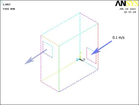
Inlet Fan Position:
The X and Y position
of the corner of the block (to create the fan) is (0.07,0.04).
Width = 0.1 m
Height = 0.1 m
The air entering the
computer is traveling 0.1m/s.
Outlet
Position: (From a plane parallel to the inlet fan at the corner farthest
from the origin)
The X and Y position
of the corner of the block (to create the outlet) is (-0.17,-0.14).
Width = 0.1 m
Height = 0.1 m
·
To best
model this system, model the volume defining the case first.
·
Then,
delete only the volume (leaving the areas, lines, and keypoints) and
create the areas defining the inlet and the outlet of the air flow.
·
Overlap
the areas to their respective faces of the computer case. (front and
back)
·
Once
the areas have been overlapped, they should then be married back into an
“arbitrary” volume. (defined “by areas”)
·
At this
point, define the Element Properties as a 3D Air Element
·
Define
the Material Properties of the Air Element (Density and Viscosity
are the important qualities)
 |
Mesh the volume
with a mesh size of 0.02 on all lines. |
|
Apply Boundary
Conditions (No Slip along the areas of the case that do not function
as an inlet or outlet, velocity into the inlet area, and Atmospheric
Pressure (P=0 in ANSYS) on the outlet area) |
|
Iterate 25 times
and solve. (Ideally the iteration count would be at least several
thousand times to make sure that the solution converges… but
computational time dictates that in order to be able to solve the
problem in a reasonable amount of time, the iteration number should be
trimmed down to 25) |
|
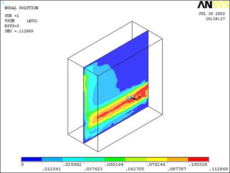
Plot
the Velocity distribution in the X and Y directions. At this point
only the outermost region of the case will be evident, so make the
workplane the “cutting plane” and show the velocity distribution along
the Z axis in the middle of the case) |
|
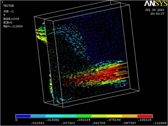
Plot
this with both a Contour Plot and a Vector Plot. |
|
This
is the answer you should obtain with 25 iterations:
|