Vibration #3:
Vibration in an Airplane Wing
Introduction:
In this example
you will execute modal analysis of an airplane wing and find its natural
frequencies.
Physical Problem:
The wing
is uniform along its length with cross sectional area as defined below.
It is firmly attached to the body of the airplane at one end.
Problem Description:
The chord of the airfoil has dimensions and orientation as shown in the
figure.
·
The
wing is made of low density polyethylene with a Young's modulus
of 38e3 psi, Poisson's ration of 0.3, and a
density of 8.3E-5 lbf-sec2/in4.
Assume the side of the wing connected to the plane is completely fixed
in all degrees of freedom. The wing is solid and material properties are
constant and isotropic.
·
The
flow velocity of air is 2m/s.
·
Objective:
To
determine the natural frequencies of vibration
To generate animations of these vibrations.
Figure:
IMPORTANT:
Convert all
dimensions and forces into SI units.
Starting ANSYS:
·
Click
on ANSYS 6.1
in the programs menu.
·
Select
Interactive.
·
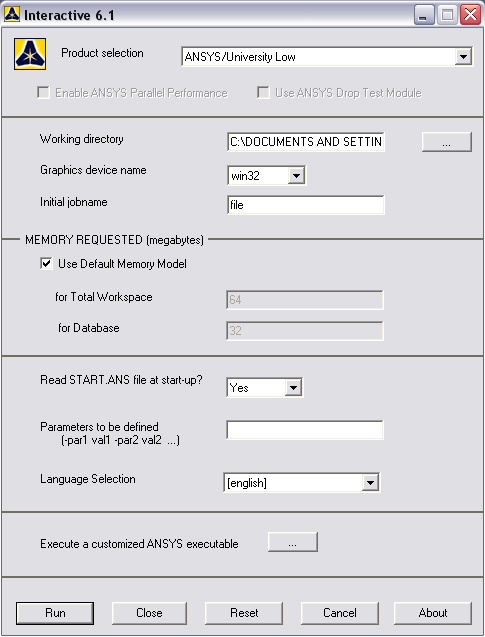
The
following menu comes up. Enter the working directory. All your files
will be stored in this directory. Also under
Use Default Memory Model make sure
the values 64 for Total
Workspace, and 32 for
Database are entered. To change these values unclick
Use Default Memory Model.
·
Click
RUN
MODELING THE STRUCTURE
·
Go to
the ANSYS Utility Menu
·
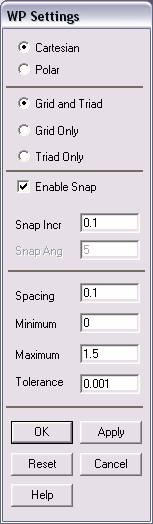
Click
Workplane>WP
Settings
·
The
following window will appear:
·
Check
the Cartesian and Grid Only buttons
Enter the values shown in the figure above.
·
Go to
the ANSYS Main Menu.
·
Choose
Utility
Menu>PlotCtrls>Pan Zoom Rotate…
and click on the enlarge button (the big black circle) five times. This
will zoom in on the center of the area, and it will be easier to select
the appropriate points below.
·
Go to
Main
Menu>Preprocessor>Modeling>Create>Keypoints>On
Working Plane.
Create the keypoints as shown in the figure
below:
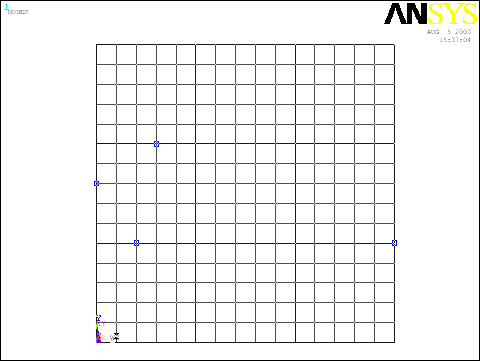
Note that I have only plotted lines before to make it easier to see the
keypoints.
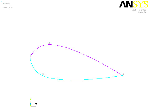
·
Go to
Main
Menu>Preprocessor>Modeling>Create>Lines>Splines
thru Keypoints
Create two splines through the top three and
the bottom three splines. The figure should
look like the one below:
·
Now
create an area enclosed by the two splines.
Go to
Modeling>Create>Areas>Arbitrary>By Lines.
·
Pick
the two splines and click OK. The
model should look like the one below.
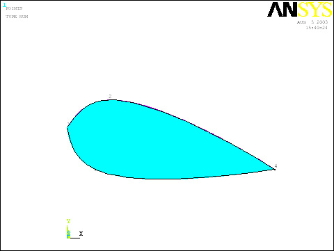
The modeling of the problem is done for now.
MATERIAL PROPERTIES
Setting preferences that are relevant to this problem:
Main Menu>Preferences
Turn on Structural filtering.
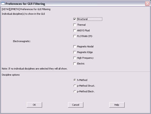
Hit OK.
MATERIAL PROPERTIES
·
Choose
Preprocessor>Material Props>Material Models
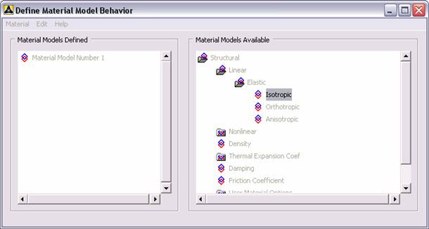
Double click Structural>Linear>Elastic>Isotropic
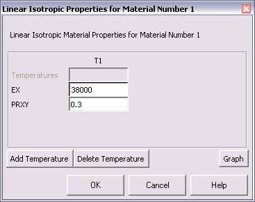
·
Enter
38000 for Young’s Modulus. Enter 0.3 for
Poisson’s Ratio
·
Also,
double click Density and input 8.3e-5
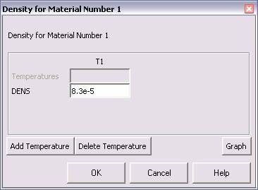
Exit Define Behavior
MESHING:
·
As opposed to the standard method we have generated, of
choosing element types in the previous stage, we will do so in this
meshing section, because it is more intuitive. In this tutorial, we are
going to first mesh the cross sectional area, using a 2D mesh..
with 2D element constraints. Then we will
extrude this element into a 3D object, and generate a 3D mesh as well,
obviously with 3D element constraints. So, we need to define two types
of elements:
·
Click
Preprocessor>Element Type>Add/Edit/Delete...
In the 'Element Types' window that opens click on Add... The
following window opens:
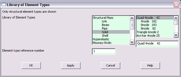
·
Click
on Structural Mass>Solid and select Quad 4node 42.
Click APPLY. Next, choose Brick
8node 45 and hit OK. Close the 'Element types' window.
·
So now we have created the appropriate material model and
the element types. Meshing will produce an appropriate model.
DIVIDING THE AREA
INTO ELEMENTS:
 |
Go to
Preprocessor>Meshing>Meshtool
|
|
Click Set on
the line with Global under Size Controls |
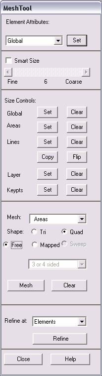
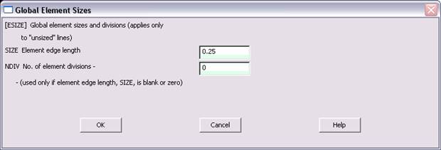
·
The
following window appears. Enter 0.25 for element edge length. Hit OK.
·
Click
Mesh, and in the Picking Dialog, choose Pick All. Note that you will
likely see a warning. Don’t worry about it. The problem is designed
taking into consideration a limit on the number of nodes that the
educational version of ANSYS we have. If we make the mesh
more fine, then when we extrude the shape,
the limit will likely be exceeded. Continue.
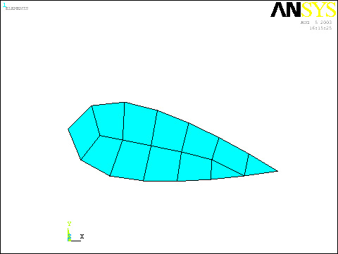
·
So far,
the mesh should appear as follows:
·
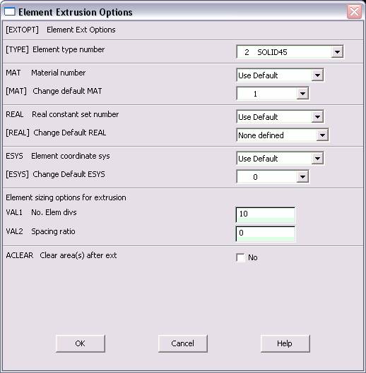
Now,
choose Main
Menu>Preprocessor>Modeling>Operate>Extrude>Elem
Ext Opts
·
Choose
2 (Solid45) for the Element type number and enter 10 for the number of
element divisions. Hit OK.
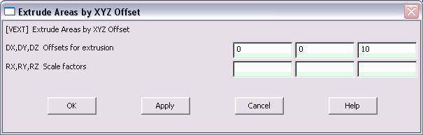
·
Now
choose Main
Menu>Preprocessor>Modeling>Operate>Extrude>Areas>By XYZ Offset
·
Select
Pick All in the selection dialog.
·
Don’t
mind the warning. If we were using a full version of ANSYS, we would be
able to choose SOLID95 instead.
·
Choose
Utility Menu>PlotCtrls>Pan
Zoom Rotate. Click on ISO and also on Fit. Hit close.
BOUNDARY CONDITIONS
AND CONSTRAINTS
|
The firs thing to
do is to unselect the Plane42 elements used in the 2D area mesh since
they wont be needed/used for the analysis.
Choose Utility Menu>Select>Entities.
|
|
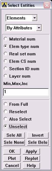
Choose Elements,
By Attributes, Elem Type
num, Enter 1 for the number, choose Unselect and hit
Apply |
·
Next,
constraints will be applied to all nodes located where the wing is fixed
to the body. Select all nodes at z = 0, then apply displacement
constraints:
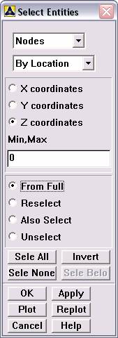
·
Choose
Nodes, By Location, Z Coordinates, enter 0 for the
value, choose From Full and hit Apply.
|
Go to
Preprocessor>Loads>Define
Loads>Apply>Structural>Displacement>On Nodes. Pick
All in the picking dialog. This will pick
all “Selected” Nodes (we just decided that already) |
|
Choose All DOF and
hit ok (by leaving the displacement value blank, we assign zero
displacement) |

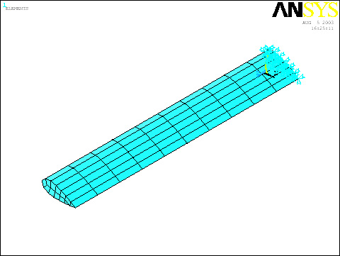
·
The
model should appear as follows, with new constraints on the end.
·
Finally, we reselect all the nodes. Return to the Select dialog that is
still open somewhere.
·
Choose
By Num/Pick, click Sele All
(Select All) and then click Cancel to close the box.
SOLUTION
|
Go to ANSYS
Main Menu>Solution>Analysis Type>New
Analysis
Choose Modal
|
·
Choose
Main Menu>Solution>Analysis Type>Analysis
Options
·
Choose
Block Lanczos and then enter 5
for the modes to extract and 5 for the modes to expand. Hit OK.


·
Click
OK again.
|
Go to
Solution>Solve>Current LS.
|
|
Click OK for the
warnings. We already addressed the fact that these warnings are
accepted. It is also ok that we did not use the Plane42 element in the
analysis, since it was only developed to create the 2D mesh we
eventually build off of. |
|
Wait for ANSYS to
solve the problem. |
|
Click on OK and
close the 'Information' window. |
POST-PROCESSING
|
Go to
General
Postproc>Results
Summary |

|
It is ok if your
results are slightly different due to mesh uniqueness. |
·
Also, we want to animate the separate modal shapes.
·
First, select the first mode.
Main Menu>General
PostProc>Read Results>First Set
·
Utility Menu>Plot
Ctrls>Animate>Mode Shape
You can pick Linear or Sinusoidal Below.

·
Choose 30 frames and .25 seconds per frame. Then select
Def+undef edge. Hit OK. Watch the first
shape:
·
Play with settings if you want. For instance, in that
animate dialog that opens, decrease the delay to 5 or so for the
animation to be more smooth.
·
To see other modes of vibration, return to General
PostProc and this time choose Read
Results>Next Set
·
Animate again with Utility Menu>Plot
Ctrls>Animate>Mode Shape
·
OK
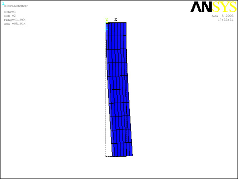
Here are files for all 5 modes: (click on the image to see/download
the file)
Note, I tried to use a view that showed the
deformations best. Try ISO for all the animations first if you want.
Also, I plotted all the deformed shapes individually using
General PostProc>Plot
Results>Deformed Shape
First
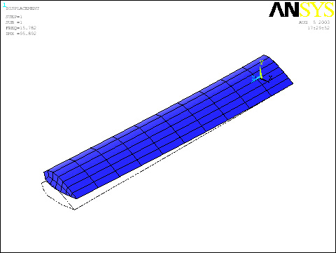 ISO
ISO
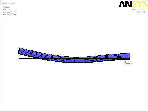
Second
 TOP
TOP
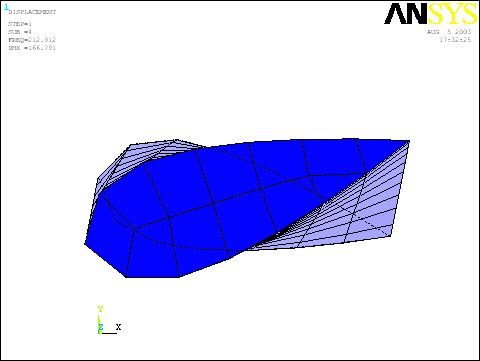
Third
 RIGHT
RIGHT
Fourth
 FRONT
FRONT
Fifth
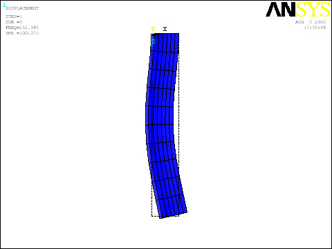 TOP
TOP