·
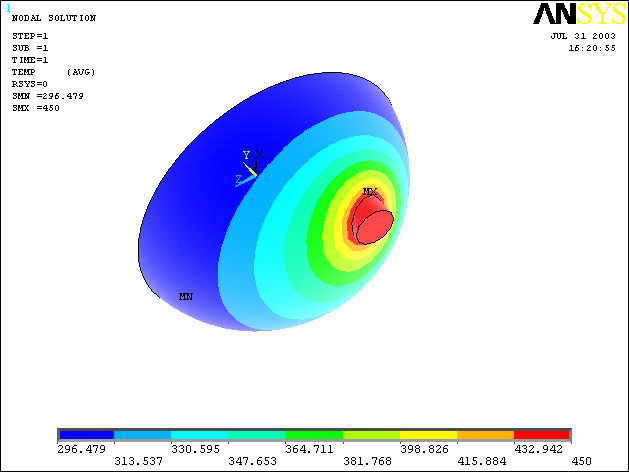
Objective:
To determine the nodal temperature distribution and create a contour
plot of the temperature gradient within the rice and vegetables.
·
Figure:
Starting ANSYS:
·
Click
on
ANSYS
6.1
in the
programs menu.
·
Select
Interactive.
·
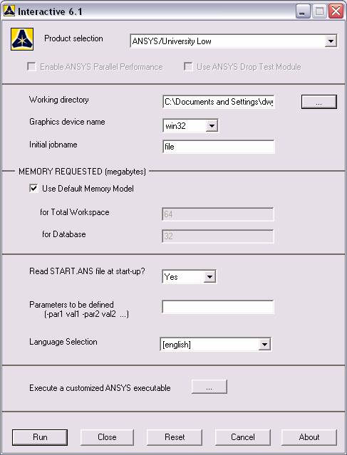
The
following menu comes up. Enter the working directory. All your files
will be stored in this directory. Also under
Use
Default Memory Model
make
sure the values
64
for Total Workspace, and
32
for Database are entered. To change these values unclick
Use
Default Memory Model.
·
Click
RUN
Modeling the Structure:
·
Go to
the ANSYS Utility Menu (the top bar)
·
Click
Workplane>WP Settings…
·
The
following widow comes up:
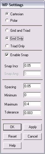
·
Check
the Cartesian and
Grid Only buttons
·
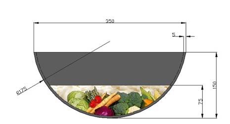
Enter
the values shown in the figure above and then click OK.
·
Go to
the ANSYS Main Menu (on the left hand side of the screen) and click
Preprocessor>Modeling>Create>Volumes>Sphere>Solid Sphere
·
Enter
the dimensions of the sphere that will constitute the food, so we can
truncate it before moving onto the wok itself. (Radius = .17 m)
·
Offset
the WP by .17 in the X and Z directions and also by
-.1125 in the Y direction. This will enable you to create
the block to subtract the extraneous portion of the sphere away. Create
a square block will dimensions equal to the diameter of the sphere,
.34 m.
·
With
the block created, use
Preprocessor>Modeling>Operate>Booleans>Subtract>Volumes
to subtract the chunk
away. Choose the sphere first, hit OK then the block. Hit OK
·
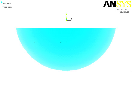
Now you
have created the volume that makes up the rice and vegetables in the
wok. If at any time you cannot see the complete Workplace then go to
Utility Menu>Plot Controls>Pan Zoom Rotate
and zoom out to see the entire Workplace. If you want to see the grid
itself, go to
Utility Menu>Workplane>Display Working Plane
·
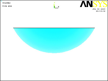
Move
the WP (offset it) back to the orginal location (move it .17+X,
.17+Z and .075+Y)
·
The
model should look like this now:
·
Now use
the same process to create the bowl. If you would like (you don’t have
to), you can move the piece of food out of the way while you make the
rest of the model. Simply change the WP snap settings to something you
will remember (like 1m) and then use
Preprocessor>Modeling>Move/Modify>Volumes and move the volume -1 in each
direction. You will still be able to see it in ISO mode, because you
moved it along that line of sight. Remember to move it back when you are
finished.
·
Remember that this time, you need to create a solid sphere of radius
.175, a second solid sphere of radius .17, and a block of lengths .35m.
Subtract the block from the big sphere and then subtract the small
sphere from what is left of the big sphere.
·
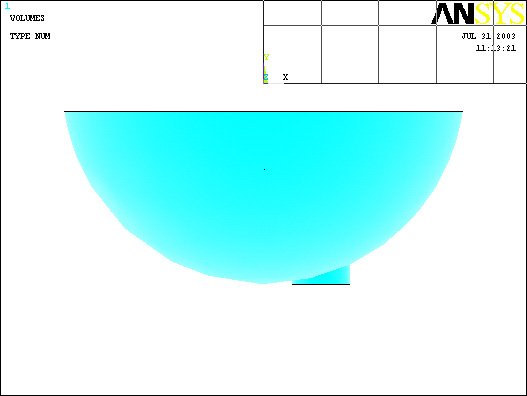
Lastly,
we want to create an area to apply heat generation to. Offset the WP
.175m in the –Y direction (to the bottom of the bowl) and rotate the WP
by 90 degrees in the –X direction. The WP will appear as follows.
·
Now
create the cylinder as follows: (note that the cylinder was created with
a length shorter than either radius of the spheres. The program did not
subtract volumes correctly when I originally modeled the cylinder with
length = .1)
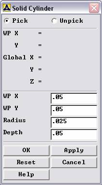
·
Create
a new sphere to use in subtracting, select .175 for the radius (remember
to offset the WP back to where it started again!)
·
Use
Preprocessor>Modeling>Operate>Booleans>Subtract>Volumes
to subtract the part
of the rod that sticks into the wok.
·
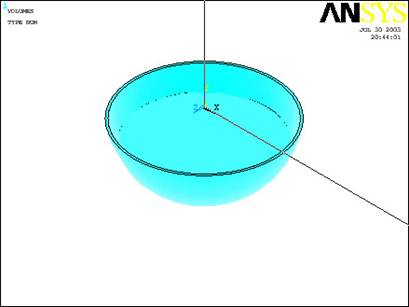
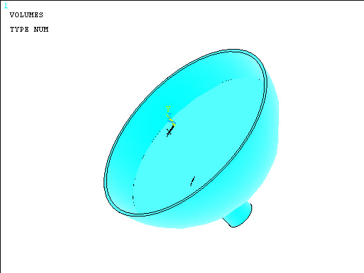
The
last step is to glue each piece together. Glue the cylinder to the bowl
and the food to the bowl.
·
(recall
that glue is found under
Preprocessor>Modeling>Operate>Booleans>Glue)
·
The
modeling is finished. See below for the general appearance of the model:
Material Properties:
·
Now
that we have built the model, material properties need to be defined
such that ANSYS understands how heat travels through the “solid” made of
rice and vegatables.
·
Go to
the ANSYS Main Menu and click
Preprocessor>Material Props>Material Models.
·
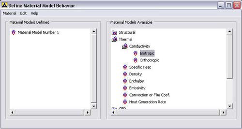
A
pop-up window that looks like this will now appear:
·
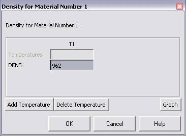
In this
window, choose
Thermal>Density.
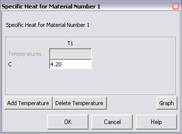
Enter 962 for the density of water. Click OK. Now, from
the Define Material Model Behavior window choose
Thermal>Specific Heat
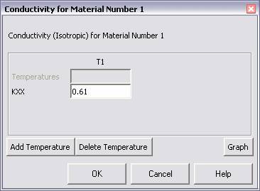
and enter 4190 for the Specific Heat of water. Again, click
OK, and from the Define Material Model Behavior window choose
Thermal>Conductivity>Isotropic
and enter 0.61 for the thermal conductivity value. The windows
that appear as result of the last sequence of commands appear as
follows:
·
Choose
Material>New Model and for the steel and air, use the properties
listed at the top of the tutorial. Repeat the processed as it was done
for the rice and vegetables above.
·
Now
exit the “Define Material Model Behavior” Window
Element Properties:
·
Now
that we’ve defined what material ANSYS will be analyzing, we have
to define how ANSYS should analyze our block.
·
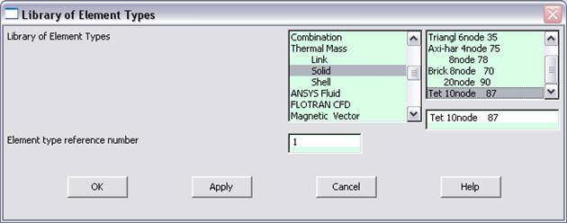
Click
Preprocessor>Element Type>Add/Edit/Delete...
In the 'Element Types' window that opens click on Add...
The following window opens:
·
Type
1 in the Element Type reference number.
·
Click
on Thermal Mass Solid and select Tet 10node 87. Click
OK.
Close the 'Element types' window.
·
Now we
have selected Element Type 1 to be a Thermal Solid 10node
Element. This finishes the section defining how the part is to be
analyzed.
Meshing:
·
This
section is responsible for telling ANSYS how to divide the block such
that it has enough nodes, or points, to analyze to make an accurate
enough analysis.
·
Go to
Preprocessor>Meshing>Size Controls>Manual Size>Lines>All Lines.
In the menu that comes up type 0.025 in the field for ”Element
edge length”.
·
Click
on
OK.
Now when you mesh the figure ANSYS will automatically create square
meshes that have an edge length of 0.025m along the lines you
selected.
·
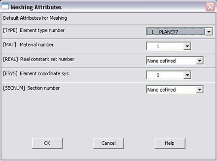
Now go
to
Preprocessor>Meshing>Mesh Attributes>Default Attributes.
The window is shown below:
·
This
window appears to select the element type and the material model. Check
that you have selected Solid and material 1 to mesh (selected by the
Element Type Number), and the right Material Number (1, as
defined in the Material Properties section). Once this has been
verified, Click OK and proceed to
Preprocessor>Meshing>Mesh>Volumes>Free
·
A popup
window will appear on the left hand side of the screen. This window
allows you to select the volume to be meshed.
·
Click
anywhere within food (you can tell if you picked right) and then click
OK
in the pop-up window.
·
Go to
Mesh
Attributes>Default Attributes
again and this time choose Material Number 2. Mesh the bowl this time.
·
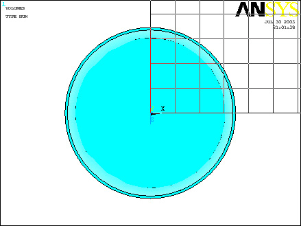
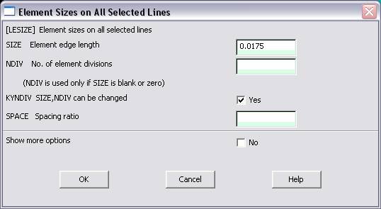
Finally, change the default attributes to material number three
and then return to ManualSize>Lines>All Lines and change the
element length to 0.0125m. Finally, mesh the small volume that
constitutes the offset burner on the stove.
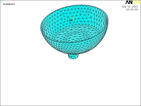
·
The
block should now look like this:
Boundary Conditions and
Constraints:
·
Now
that we have modeled the block and defined how ANSYS is to analyze the
block we will apply the appropriate Boundary Conditions. ANSYS refers
to all Thermal Boundary Conditions as Loads, so be aware that Load and
Boundary Condition mean the same thing within the software…
·
Go to
Preprocessor>Loads>Define Loads>Apply>Thermal
(from here one can apply any of the loads, or Boundary Conditions,
offered by ANSYS.)
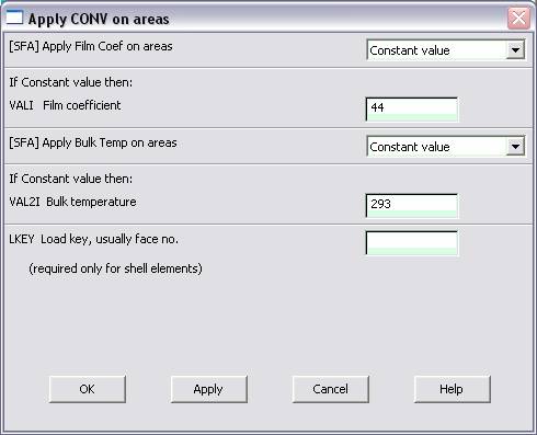
Apply Convection (Top)
·
First
we’ll apply the Convection Boundary layer at the top of the
plate. For this click Convection>On Areas
within the Thermal Load category.
·
A popup
window will appear on the left hand side of the screen. This window
allows you to select the areas you wish the load to be applied.
·
Select
the top rim of the wok and the inside walls of the wok. hit
OK. The following window will
appear:
·
Fill in
the h value in the Film Coefficient blank and the Air
temperature in the Bulk Temperature blank. Click
OK when finished.
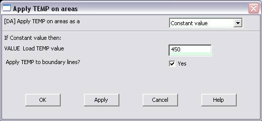
Apply Temperature (Bottom
Area of Cylinder)
·
Now to
apply the Heat Flux into the bottom of the plate...
·
Within
the Thermal Load category again, select
Temperature>On Areas and click
OK.
·
This
window will now appear:
·
Then
enter 1000 into the blank and Click
OK.
Solution: