Thermal #1: Temperature
distribution in a fin cooled electronic component
Introduction:
In this
example you will learn to model a cooling fin for electronics. This
involves heat generation, conduction and convection.
Physical Problem:
All
electronic components generate heat during the course of their
operation. To ensure optimal working of the component, the generated
heat needs to be removed and thus the electronic component be cooled.
This is done by attaching fins to the device which aid in rapid heat
removal to the surroundings.
Problem Description:
 |
For the sake of
simplicity we assume that the electronic circuit is made of copper
with thermal conductivity of 386 W/m K. Also it generates heat at the
rate of 10e6 W. |
|
The enclosing
container is made of steel with thermal conductivity of 20 W/m K.
|
|
The fins are made
of aluminum with thermal conductivity of 180 W/m K. |
|
Units: Use
S.I. units ONLY |
|
Geometry:
See figure. |
|
Boundary conditions:
There is convection along all the boundaries except the bottom, which
is insulated. The Film Coefficient is 50 W/m2K and the Bulk
Temperature is 20oC. |
|
Objective:
 |
To determine the
nodal temperature distribution. |
|
To determine the
maximum value of temperature in the component. |
|
|
You are required to
hand in print outs for the above. |
|
Figure:
|
IMPORTANT:
Convert
all dimensions and forces into SI units.
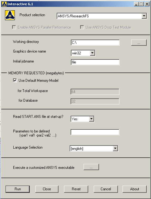
STARTING ANSYS
Click
on ANSYS 6.1in the programs menu.
Select
Interactive.
The
following menu that comes up.
Enter the working directory. All your files will be stored in this
directory. Also enter 64 for Total Workspace and 32 for
Database.
Click
on Run.
MODELING THE STRUCTURE
|
Go to the ANSYS
Utility Menu.
|
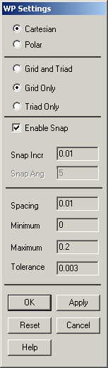
Click
Workplane>WP
Settings.
|
|
The following
window comes up |
|
|
Check the
Cartesian and Grid Only buttons. |
|
Enter the values
shown in the figure below. |
|
Go to the ANSYS
Main Menu
Preprocessor>Modeling>Create>Areas>Rectangle>2 Corners.
|
|
The following
window comes up: |

|
Now we will pick
the end points of the rectangles. |
|
First make the
steel rectangle of dimensions 5cm X 3 cm, i.e. 5 units by 3 units on
the grid. |
|
Next make the
copper square of dimensions 1cm X 1cm. |
|
Next make the
aluminum part by making a rectangle of dimensions 5cm X 2cm and then
creating two smaller rectangles, which can then be subtracted from the
main part to make the fins. |
|
From Preprocessor,
choose
Modeling>Operate>Boolean>Overlap>Areas.
Choose the Steel area and then the Copper area,
then click OK. |
|
From Preprocessor,
choose
Modeling>Operate>Boolean>Glue>Areas.
Choose the Steel area and then the Aluminum area, and then click OK.
The reason why we don’t glue the copper and the steel is that they
overlap. Picture a copper plate resting on the steel area. The steel
and aluminum are connected more intimately, and must be glued
together. |
|
If you cannot see
the complete workplane then go to
Utility Menu>Plot Controls>Pan Zoom Rotate
and zoom out to see the entire workplane.
|
|
The model should
look like the one below. |
MATERIAL PROPERTIES
|
We need to define
material properties separately for steel, aluminum, and copper.
|
|
Go to the ANSYS
Main Menu |
|
Click
Preprocessor>Material Props>Material Models.
In the window that comes up choose
Thermal>Conductivity>Isotropic.
|

|
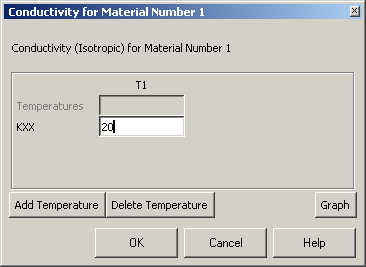
Enter 1 for the
Material Property Number and click OK. The following window comes up.
|
|
Fill in 20
for Thermal conductivity. Click OK. |
|
Now
the material 1 has the properties defined in the above table. This
represents the material properties for steel. Repeat the above
steps to create material properties for aluminum (k=180,
Material number 2), and copper (k=386, Material number 3). Do
this by selecting
Material>New Model
in the “Define
Material Model Behavior” window. |
ELEMENT PROPERTIES
|
SELECTING ELEMENT
TYPE: |
|
Click
Preprocessor>Element Type>Add/Edit/Delete...
In the 'Element Types' window that opens click on Add... The following
window opens. |
|
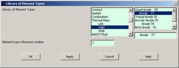
Type 1 in
the Element type reference number. |
|
Click on Thermal
Mass Solid and select Quad 8node 77. Click OK. Close the
'Element types' window. |
|
So now we have
selected Element type 1 to be a thermal solid 8node element. The
component will now be modeled with thermal solid 8node elements. This
finishes the selection of element type. |
MESHING
|
DIVIDING THE TOWER
INTO ELEMENTS: |
|
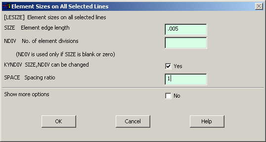
Go to
Preprocessor>Meshing>Size Controls>Manual Size>Lines>All Lines.
In the menu that comes up type 0.005 in the field for 'Element edge
length'. |
|
Click on OK. Now
when you mesh the figure ANSYS will automatically create meshes that
have an edge length of 0.005m along the lines you selected.
|
|
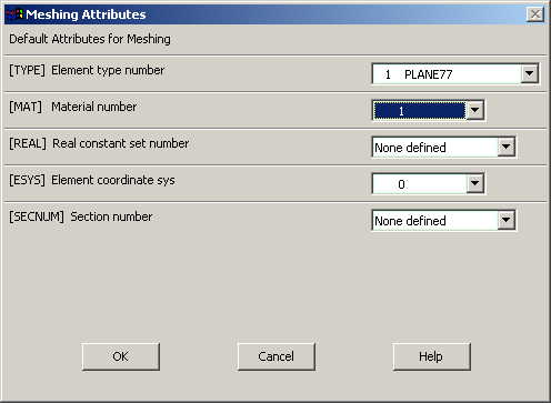
First we will mesh
the steel area. Go to
Preprocessor>Meshing>Mesh Attributes>Default Attributes.
Make sure the window indicates "Material Ref.#1".
The window is shown below. |
|
Now go to
Preprocessor>Meshing>Mesh>Areas>Free.
Pick the steel area and click OK. |
|
Repeat the same
process for the aluminum and copper areas. Make sure you use the
correct material number (2 and 3 respectively) for both the areas.
Also since the steel and the copper areas overlap make sure you pick
the right area. If you choose the wrong area, use
Preprocessor>Meshing>Clear
to undo the previous mesh and then repeat the previous steps. The
meshed area should look like this: |
BOUNDARY CONDITIONS AND
CONSTRAINTS
|
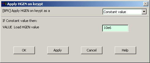
Go to
Preprocessor>Loads>Define Loads>Apply>Thermal>Heat Generate>On
Keypoints.
|
|
Select the corners
of the copper square. Click OK. The following window comes up.
|
|
Enter 10e6
for the HGEN value and click OK. |
|
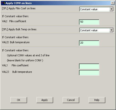
Go to Preprocessor>Loads>Define
Loads>Apply>Thermal>Convection>On Lines.
Pick all the lines on the outside of the object except the bottom one
where the object is considered insulated. Click OK. The following
window comes up. |
|
Enter 50 for
"Film Coefficient" and 20 for "Bulk Temperature" and click OK.
|
|
Now the Modeling of
the problem is done. |
SOLUTION
|
Go to ANSYS
Main Menu>Solution>Analysis Type>New Analysis.
|
|
Select Steady
State and click on OK. |
|
Go to
Solution>Solve>Current LS.
|
|
An error window may
appear. Click OK on that window and ignore it. |
|
Wait for ANSYS to
solve the problem. |
|
Click on OK and
close the 'Information' window. |
POST-PROCESSING
|
Listing the
results. |
|
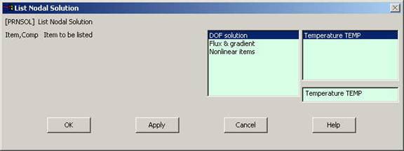
Go to ANSYS Main
Menu
General Postprocessing>List Results>Nodal
Solution.
The following window will come up. |
|
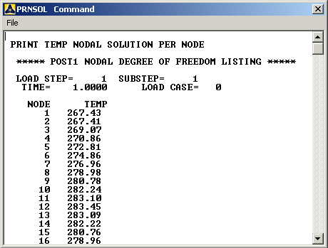
Select DOF
solution and Temperature. Click on OK. The nodal
displacements will be listed as follows. |
|
You will find the
maximum value of temperature at the end of the above table.
|
MODIFICATION
|
You can also plot
the displacements and stress. |
|
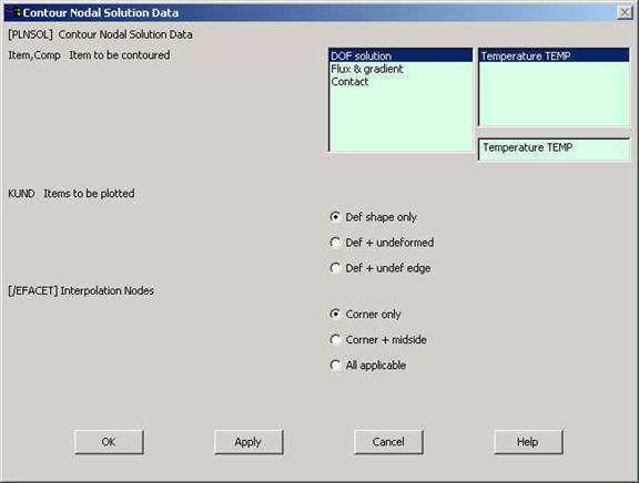
Go to
General Postprocessing>Plot
Results>Contour Plot>Nodal Solution.
The following window will come up: |
|
Select DOF
solution and Temperature to be plotted and click OK. The
output will be like this: |