Structural #6: Analysis
of a 3D solid object
Introduction:
In this
example you will learn to use the Solid element in ANSYS. Also you will
learn some basic 3D modeling.
Physical Problem: See
figure.
Problem Description:
 |
We will model the
object using solid Tetrahedral 10 node element. |
|
Material:
Assume the structure is made of steel with modulus of elasticity E=200
GPa.
|
|
Boundary conditions:
The object is fixed around the inner surface of the hole. |
|
Loading:
The object is loaded uniformly (1000 N/cm2)
along
the top surface of the extended beam. |
|
Objective:
 |
To plot deformed
shape. |
|
To determine the
principal stress and the von Mises
stress. (Use the stress plots to determine these. Do not print the
stress list) |
|
What is the
maximum load the object can take. Clearly
mention the yield stress that you have assumed for steel. Also
assume factor of safety of 1.25. |
|
|
You are required to
hand in print outs for the above. |
|
Figure: |
STARTING ANSYS:
|
Click on ANSYS
6.1 in the programs menu. |
|
Select
Interactive. |
|
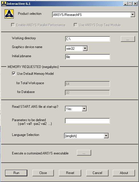
The following menu
that comes up. Enter the working directory. All your files will be
stored in this directory. Also enter 64 for Total Workspace and
32 for Database. |
|
Click on Run.
|
MODELING THE STRUCTURE:
|
Go to the ANSYS
Utility Menu. |
|
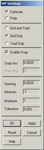
Click
Workplane>WP
Settings.
|
|
The following
window comes up: |
|
Check the Cartesian
and Grid Only buttons. |
|
Enter the values
shown in the figure above. |
|
We will model the
object as four seperate volumes and then
add them up. |
|
Go to the ANSYS
Main Menu
Preprocessor>Modeling>Create>Volumes>Blocks>By
2 corners & Z.
|
|
Select the two
corners and enter the depth in the "depth "
field so as to create the first rectangular part of the figure. The
isometric view looks like the figure below. |
|
Now create two
cylinders representing the holes. Use the
Preprocessor>Modeling>Create>Volumes>Cylinder>Solid
Cylinder,
and select the center and the radius and the depth of the cylinder.
|
|
Now subtract these
two cylinders from the main rectangular block. Use the
Preprocessor>Modeling >Operate>Booleans>Subtract>Volumes
menu. Select the base area first (the rectangular block). Then select
the volumes to be subtracted (the two cylinders). Click OK. The
isometric view of the figure looks like the figure below. |
|
Now we will create
the extended portion of the object. |
|
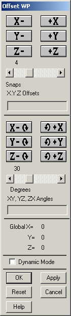
Go to
Utility Menu>WorkPlane>Offset
Workplane by Increments.
The following window will come up. |
|
Now offset the
workplane in the +Z direction by an amount
equal to the thickness of the previous rectangular block we made. This
thickness is 0.01 m which is 4 times of the snap (0.0025). So we set
the 'snaps' to 4 and click on the +Z once. The
workplane looks like this from the left
side view. |
Now
create the first extended rectangular block. The figure will look like
the one below in isometric view.
|
Now offset the
workplane further along the +Z axis by an
amount equal to the length of the extended block (0.06 meter).
|
|
So the
workplane looks like this from the left
side view. |
|
Now create another
block (block 3) by |
|
Preprocessor>Modeling>Create>Volumes>Blocks>By
2 corners & Z.
|
|
We make this block
separately so that we can create the required fillet easily.
|
|
Now create the
block 4. |
|
Now glue parts
together. Go to
Preprocessor>Modeling>Operate>Booleans>Glue>Volumes.
|
|
In the window that
comes up click Pick All and click OK. |
|
Now we will create
the fillet. Go to
Preprocessor>Modeling>Create>Lines>Line
Fillet
Select two lines on the "L" shape to create Fillet in between. Do this
for both top and bottom sides. See the Figure below: |
|
Now create two
lines. Go to
Preprocessor>Modeling>Create>Lines>Lines>Straight
Line.
Pick keypoints to create lines as shown in
the figure below: |
|
Now, create areas
to close the fillet.
Go to
Preprocessor>Modeling>Create>Areas>Arbitrary>By
Lines
Create 3 areas of the fillet (Top, Bottom and Front) as shown in
Figure below |
|
Two more areas are
needed to define the fillet volume.
Go to
Operate>Booleans>Divide>Area by Line.
Select the inner area of the "L" shape click OK. |
|
Then select the
line as shown to divide the area into two pieces and click OK
|
|
Repeat the dividing
areas steps for the other inner area of the "L" shape
|
|
Now create the
volume within the fillet by
Preprocessor>Modeling>Create>Volumes>Arbitrary>By
Areas.
Select the areas which enclose the fillet volume and click OK. The
final model will look as follows. |
|
Now go to
Preprocessor>Modeling>Operate>Booleans>Add>Volumes.
Click on Pick All. So now we have added all the volumes into a
single volume. |
MATERIAL PROPERTIES:
|
Go to the ANSYS
Main Menu |
|
Click
Preprocessor>Material Properties>Material Models.
In the window that comes up, select
Structural>Linear>Elastic>Isotropic.
|

|
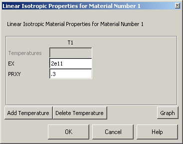
Material model 1 is
automatically selected. The following window comes up |
|
Fill in 2e11
for the Young's modulus and 0.3 for minor Poisson's Ratio.
Click OK. |
|
Now the material 1
has the properties defined in the above table. We will use this
material for the structure. |
ELEMENT PROPERTIES:
|
SELECTING ELEMENT
TYPE: |
|
Click
Preprocessor>Element Type>Add/Edit/Delete...
In the 'Element Types' window that opens click on Add... The following
window opens: |

|
Type 1 in
the Element type reference number. |
|
Click on
Structural Solid and select Tet
10node 92. Click OK. Close the 'Element types' window. |
MESHING:
|
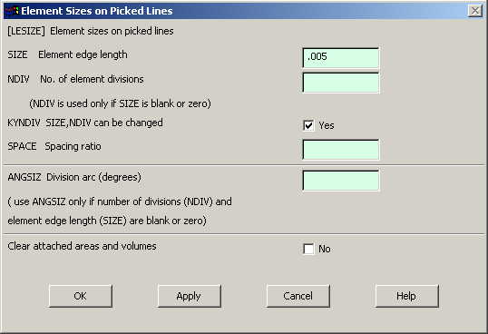
Go to
Preprocessor>Meshing>Size Controls>Manual Size>Lines>Picked
Lines. Pick
all the lines on the outer boundary of the figure and click OK.
|
|
In the menu that
comes up type 0.005 in the field for 'Element edge length'.
|
|
Click on OK.
|
|
Now go to
Preprocessor>Meshing>Mesh>Volumes>Free.
|
|
Click Pick All
in the "Mesh Areas" dialog box. The meshed model looks like this.
|
|
Now the object is
divided into Solid Tetrahedral elements. |
BOUNDARY CONDITIONS AND
CONSTRAINTS:
|
APPLYING BOUNDARY
CONDITIONS |
|
The object is fixed
around the inner faces of the holes. |
|
Go to Main Menu
Preprocessor>Loads>Define Loads>Apply>Structural>Displacement>On
Areas.
|
|
Select the areas on
the inner surface of the holes and click OK. The following window
comes up. |

|
Select All DOF and
click OK. The holes will look like the following after zooming in.
|
|
APPLYING FORCES
|
|
Go to the Main Menu
|
|
Click on
Preprocessor>Loads>Define Loads>Apply>Structural>Pressure>On
Area.
|
|
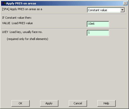
Select the top
surface of the cantilever like arm. |
|
Click on OK in the
'Apply PRES on areas' window. The following window will appear:
|
|
Enter the value of
the pressure as shown above. |
|
Click OK.
|
|
The model should
look like the one below. |
|
Now the Modeling of
the problem is done. |
SOLUTION:
|
Go to ANSYS
Main Menu>Solution>Analysis Type>New Analysis.
|
|
Select Static
and click on OK. |
|
Go to
Solution>Solve>Current LS.
|
|
Wait for ANSYS to
solve the problem. |
|
Click on OK and
close the 'Information' window. |
POST-PROCESSING:
You can
also plot the displacements and stress.
Go to
General Postprocessing>Plot Results>Deformed
Shape.
The following window comes up:
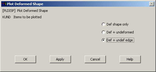
Select
Def+undef edge and click OK.
The output will be like the figure below
Select
a stress (say von Mises) to be
plotted and click OK. The output will be like this.