·
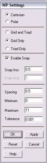
Check
the Cartesian and Grid Only buttons
·
Enter
the values shown in the figure above.
In this problem we
will model the mountain range, then model the wind around it, then
subtract the volume of the mountains from the block of air. At this
point we will then apply fluid flow to the air over the mountains and
see how its flow is impeded due to the shape of the “Rocky Mountains.”
·
Now, we
will create the model.
·
Click
Preprocessor>-Modeling->
and create the volume to define the air around the mountains.
·
NOTE:
It makes the creation of the mountain range easier to go to the ANSYS
Main Menu (the top bar) and select PlotCntrls>Pan
Zoom Rotate and select the Isometric view (ISO). This simply
allows you a better view of the 3 dimensional volumes as you form them.
·
Once
the outer volume is finished, rotate the working plane 90°
along the X axis such that it’s situated at the base of the cube.
·
Once
the plane is in place, create the 2 Conic Volumes ”By Picking”.
·
Enter
the values given in the problem description for each Cone position and
dimensions.
·
Once
the cones have been created, go to
Preprocessor>Modeling>Operate>Boolean>Add
and add the volumes
such that both cones become one volume.
·
This
volume is then to be subtracted from the bigger cube such that the space
where the mountains would be is now an empty volume. This is because
the large cube is defined as a section of air around the mountain
range. This air never penetrates the mountain, so the volume of air is
represented as a large cube with the mountain section removed.
·
At this
point, the finished model should look like this: (If you plot lines, not
volumes)
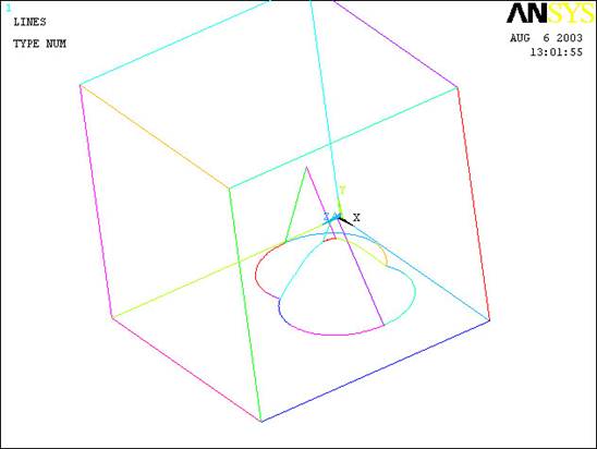
The modeling of the
problem is done.
ELEMENT PROPERTIES
SELECTING ELEMENT
TYPE:
·
Click
Preprocessor>Element Type>Add/Edit/Delete...
In the 'Element Types' window that opens click on Add... The
following window opens:
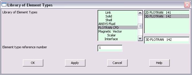
·
Type
1 in the Element type reference number.
·
Click
on Flotran CFD and select
3D Flotran 142. Click OK. Close
the 'Element types' window.
·
So now
we have selected Element type 1 to be a Flotran
element. The component will now be modeled using the principles of fluid
dynamics. This finishes the selection of element type.
DEFINE THE FLUID
PROPERTIES:
·
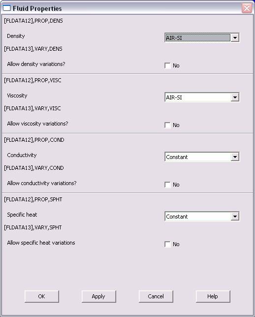
Go
to
Preprocessor>Flotran Set Up>Fluid
Properties.
·
On the
box, shown below, make sure the first two input fields read AIR-SI,
and then click on OK. Another box will appear. Click OK
to accept the default values.
·
Now
we’re ready to define the Material Properties
MATERIAL PROPERTIES
·
Go to
the ANSYS Main Menu
·
Click
Preprocessor>Material Props>Material Models.
The following window will appear
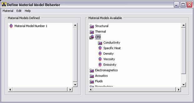
·
As
displayed, choose CFD>Density. The following window appears.
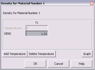
·
Fill in
1.23 to set the density of Air. Click OK.
·
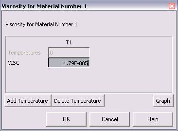
Now
choose CFD>Viscosity. The following window appears:
·
Fill in
1.79e-5 to set the viscosity of Air. Click OK
·
Now the
Material 1 has the properties defined in the above table so the Material
Models window may be closed.
MESHING:
DIVIDING THE CHANNEL
INTO ELEMENTS:
·
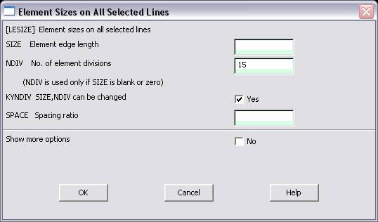
Go to
Preprocessor>Meshing>Size Cntrls>ManualSize>Lines>All
lines.
·
In the
window that comes up type 15 in the field for 'No. of element
divisions'.
·
Now go
to
Preprocessor>Meshing>Mesh>Areas>Free.
Click Pick All. The mesh will look like the following.
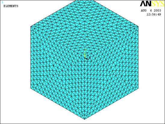
NOTE: The mountains
are meshed safely inside the block. Do not be alarmed that you can not
see them.
BOUNDARY CONDITIONS
AND CONSTRAINTS
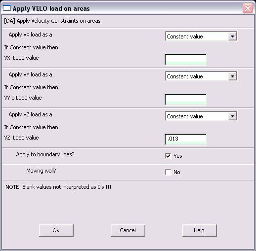
1.
Go to
Preprocessor>Loads>Define Loads>Apply>Fluid CFD>Velocity>On Areas.
Pick the area of the square that forms the XY plane intersecting with
the origin and Click OK. The following window comes up.
·
Enter
0.013 in the VZ value field and click OK. The 0.013 corresponds
to the velocity of 13 meters per second of air flowing over the
mountains scaled down by 1000.
·
Then,
set the Velocity to ZERO along all of the areas defining the
mountains and the ground. This is because of the “No Slip Condition”
acting on those surfaces. (VX=VY=0 for all sides)
·
Go to
Main
Menu>Preprocessor>Loads>Define Loads>Apply>Fluid CFD>Pressure DOF>On
Areas.
Pick the areas without previously defined boundary conditions (ie:
the Top, Sides, and face opposite the face with the velocity applied)
and click OK.
·
Enter
0 as the pressure value. (This sets the pressure as atmospheric
allowing the air to pass over the mountain range)
·
Once
all the Boundary Conditions have been applied, we can move on to solving
the problem.
SOLUTION
·
Go
to ANSYS
Main
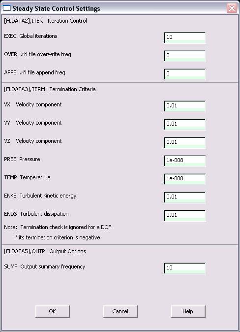
Menu>Solution>Flotran Set Up>Execution Ctrl.
·
The following window appears. Change the first input field value to
10, as shown. No other changes are needed. Click OK.
·
Go
to
Solution>Run FLOTRAN.
·
Wait for ANSYS to solve the problem.
·
Click on OK and close the 'Information' window.
POST-PROCESSING
·
Plotting the velocity distribution…
·
Go
to
General
Postproc>Read
Results>Last Set.
·
Then go to
General
Postproc>Plot
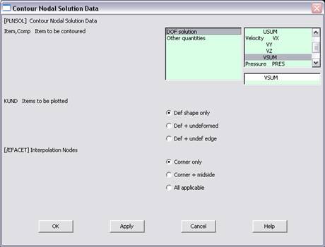
Results>Contour Plot>Nodal Solution.
The following window appears:
·
Select DOF Solution and Velocity and Click OK.
·
This is what the solution should look like:
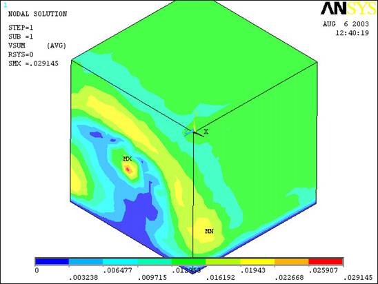
Despite what you may think this is the correct solution. Now, in order
to view the effects of the air flow on the mountains within the block of
air we must move the working plane so that it’s positioned along the Z
axis and tell ANSYS to show a cut away view using the workplane as it’s
cutting plane. This is how you accomplish that: