2.3 Apply Loads
In this problem, two forces are applied on different side of the pedal crank, causing bending moment, axial stress, and shear stress. A 914.28 lb force is applied upwards on one side of the pedal crank, while the 1114.28 lb force is applied downward to the opposite side of the pedal crank.
Applying 914.28 lb force
PREPROCESSOR -> Loads
LOADS -> DefineLoads
DEFINE LOADS ->Apply
APPLY -> Structural Force/Moment
STRUCTURAL FORCE/MOMENT-> On Nodes
Click on the node as shown
Select
FY and Constant Value and enter in 914.28. Now
the arrows should appear as in the figure below.
Repeat the same step for the node on the other side.
Select the following node.
Then enter -1114.28
for
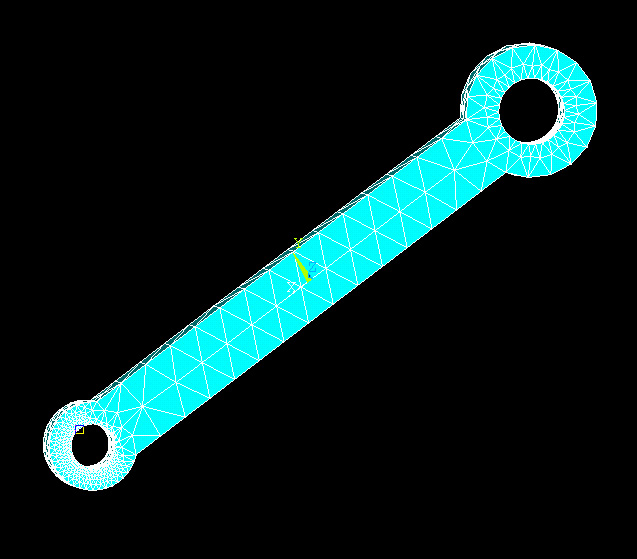
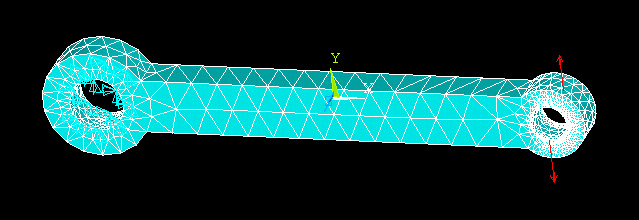
constant FY. You should now see the two forces being applied to the pedal
crank.
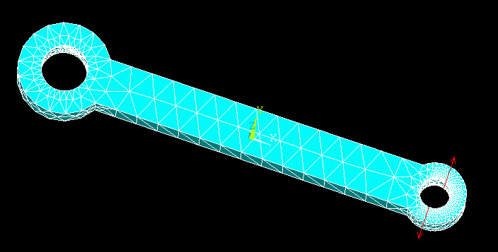
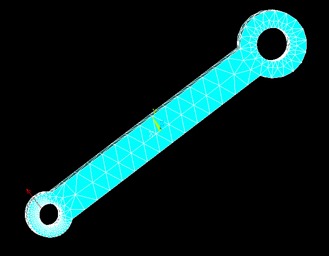
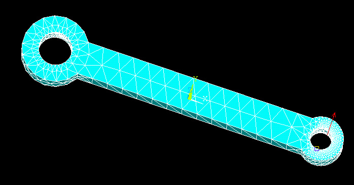
The next step is to apply boundary conditions. Here we can fix the displacements
on inner arcs of the hole on the opposite side to where the loads are being
applied.
PREPROCESSOR -> Loads
LOADS -> DefineLoads
DEFINE
LOADS ->Apply
APPLY -> Structural Displacement
STRUCTURAL DISPLACEMENT -> On Lines
Then click on two circular arcs on both side of the pedal crank.
Select
ALL DOF and enter 0 in the displacement
value box. After applying loadings, the part should look like this.
The model is now ready to be analyzed.