4A. Apply Boundary Conditions
APPLY -> Displacements
This section tells the program what boundary conditions are to be applied
to the beam. Since the beam is to be simply supported you want one end constrained
in both the x and y directions and the other only constrained in the y direction.
PREPROCESSOR -> Loads
LOADS -> DefineLoads
DEFINE
LOADS ->Apply
DISPLACEMENTS -> On Lines
ANSYS GRAPHICS WINDOW -> With the left mouse button, select the node on
the neutral axis (horizontal line passing through the middle of the beam)
which is on the far left edge of the beam. Click
APPLY in the U,ROT ON LINES window.
APPLY U,ROT ON LINES -> Select All DOF and
enter zero for displacement value and click APPLY. This constrains
the chosen line on the beam from moving in any direction.
Repeat the above procedure for the right edge of
the beam except un-select ALL DOF, and select UY
for DOFs to be constrained. That will allow the right end to translate in
the x direction but not in y direction.
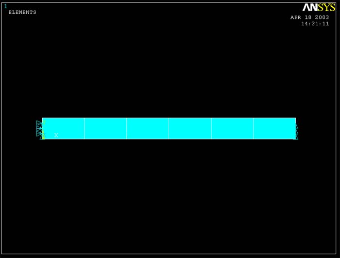
The screen should now look like the figure below with arrows marking the points
which are limited to zero displacement.