3. Mesh the Object
Meshing the part
means breaking the part into smaller pieces (elements) so that the program
can analyze the loadings (stresses, temperatures, velocities, etc.) within
the part. Breaking the part into many, small pieces (a fine mesh) will generally
give more accurate results, but will use up more time and memory. Using fewer,
larger pieces (a coarse mesh) will allow the model to run more quickly and
use less memory, but will give less accurate results. In general it is good
to start out with a coarse mesh and keep refining it in order to get the desired
amount of accuracy.
We
want to mesh the member into 6 elements. Thus, we choose an element of size
2x4. So, we have to mesh the lines parallel to the Y-axis into 6 segments
and the lines parallel to the X-axis into 1 segment.
MAIN MENU -> Preprocessor
PREPROCESSOR -> -Meshing -Size Contrls
SIZE
CNTRLS -> Manual Size
MANUAL SIZE -> Line
-Picked Lines
ELEMENT SIZE ON PICKED LINES -> Click on the top and bottom
lines of the beam.
ELEMENT SIZE ON PICKED LINES -> Click OK.
ELEMENT SIZE ON PICKED LINES -> Enter 6 in the NDIV box, then click OK.
SIZE CNTRLS -> Manual Size
MANUAL SIZE -> Line -Picked Lines
ELEMENT SIZE ON PICKED LINES -> Click on the two vertical segments
of the beam.
ELEMENT SIZE ON PICKED LINES -> Click OK.
ELEMENT SIZE ON PICKED LINES -> Change 6 to a 1 in the NDIV box, then click
OK.
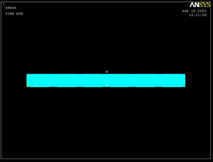
You are now ready to mesh the beam. You can see from figure below that the
lines are meshed into the desired segments, the letter "M" indicates
that the lines have been meshed.
MAIN MENU -> Preprocessor
PREPROCESSOR -> -Meshing -Mesh
MESH -> -Area -Mapped
MAPPED
-> 3 or 4 Sided
MESH
AREAS -> Click on the beam. It will change color. Click OK.
MESH
AREAS -> Click APPLY.
MESH
AREAS -> Click OK.
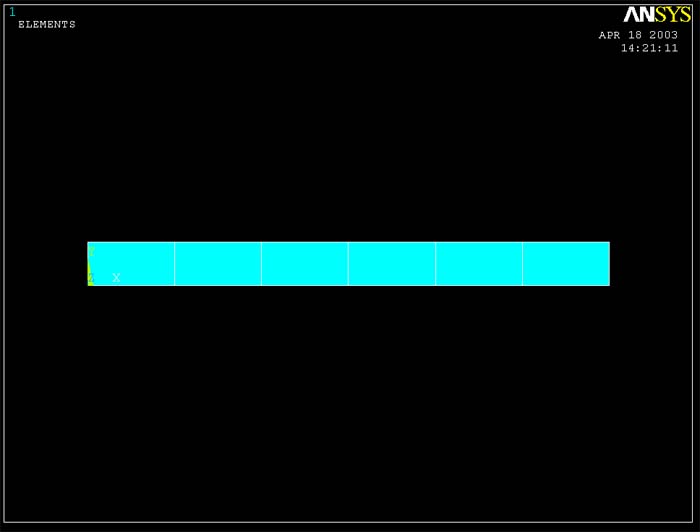
Wait for the program to mesh the part - this may take several seconds. The
part will now appear broken down into a six element mesh, with six elements
along the length of the beam and one element through the thickness.
Close the MESH window.