Lab 6: DC and Servo Motors
This lab has three purposes. Firstly to introduce Arduino shields and use a motor shield to control a DC motor, secondly to introduce the control of servo motors, and thirdly to introduce the use of the serial terminal to send commands to the Arduino.
Before starting the lab please be sure that you have the your Arduino, Motor Shield, and Arduino IDE installed.
Part List:
(1) 9v Battery
(1) 9v Battery Cap/Connector
(1) DC Motor
(1) Push Button & Resistor
(1) Potentiometer
(1) Servo
Part 1: DC Motor
Connections
Stack the motor shield on top of the Arduino. Now we just need to connect power to the shield, connect the motor, and then we're off. Using the 9V battery cap that came in your kit and your 9V battery, connect power to the Arduino barrel jack. Make sure that the motor shield power jumper is in place (it should already be when you get it).
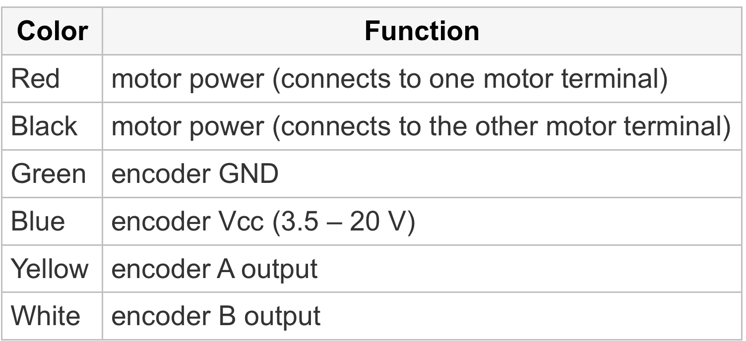
Now let's connect the motor. Screw down two wires to the two terminals at M1 (do not connect to ground!). Now connect those wires to the motor power. Recall that the pinout for the motor is:
Code
The provided code communicates with the motor shield to bi-directionally drive the motor. The shield uses I2C, a serial communication protocol, and features an easy to use library to drive DC motors, steppers, and servo motors. In this code we just use the library to drive the motor with varying speeds in both directions. This shows the base functionality of the shield, including specifying PWM signals and direction changes.
If you haven't already, please download the motor shield library from this link.
Unzip the file and place in your libraries folder of your main Arduino folder. Quit and reopen Arduino IDE. Now you should be able to use the motor shield library.
Now load the 1st sample code for the lab and watch the motor spin.
NOTE: You should not keep your motor spinning continuously. This will drain your battery pretty quickly, so just spin for a little while and then power down.
Your Turn
Connect a push button and potentiometer to your Arduino. Modify the code so that the state of the push button determines the direction of the motor and the potentiometer varies the speed.
Part 2: Servo Motor
Connections
Connecting a servo motor is simple - just power, ground and "PWM". The pinout from Tower Pro is below. You can simply make Vcc = 5V. Connect the PWM pin to Pin 9 on the Arduino to match the sample code. You should also connect a servo horn to your motor so you can watch the angle change.
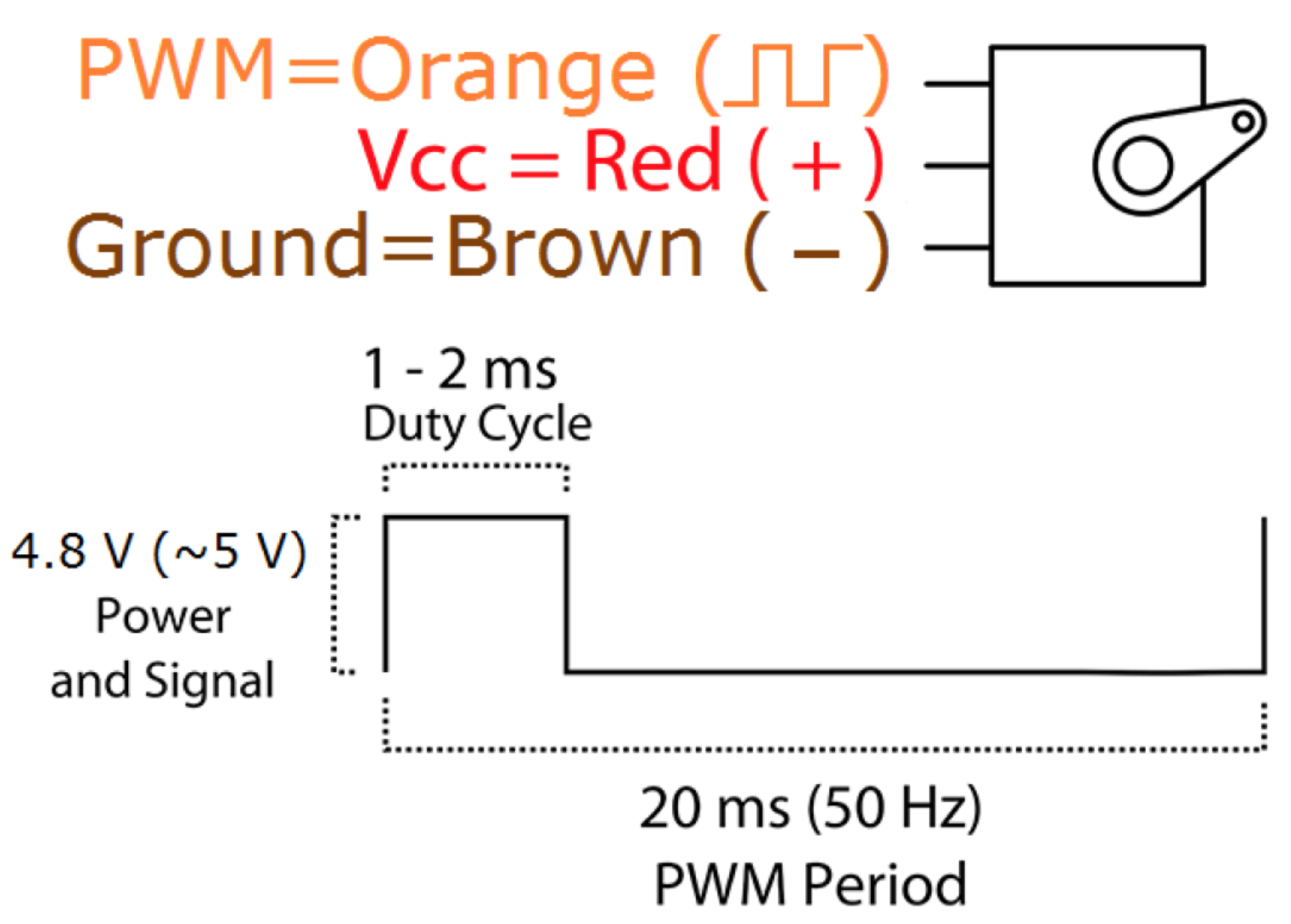
Figure 1: Pinout from the Tower Pro SG90 datasheet.
Code
This code uses the Arduino servo library for simplicity. The code reads the value of angle you enter in the serial terminal and turns the servo horn to the desired angular location. Note that you should enter the vales of the angle in 3-digit format. (Eg: '120', '090', '010', '005' etc.)
NOTE: when you use the servo library, you lose the ability to use the timer interrupts as in Mini-lab 5. You also lose analogWrite capability on pins 9 and 10. The servo library uses the same timer that was used in Timer1.h, so there is a conflict. This is because the "PWM" signal is not generated using analogWrite. The frequency is much too low for PWM, and the duty cycle only ranges between 5% and 10% over the full rotation range of the servo. The servo library essentially sets up a timer interrupt that occurs every 20 ms and sends a pulse ranging from 1 - 2ms to the pins.
Your Turn
1] Now recall the code to read the encoders from the last lab. Leveraging that code, use the rotation of the DC motor to control the angle of the servo motor.
2] Limit your rotation angles to match the achievable range by the servo.
3] Now spin the motor, show the TA that the servo follows, and you're done!