24-351
Fall 2000
Homework 2: Adams Assignment
In this assignment, you are going to solve a problem from J.L Meriam, Dynamics, 3rd edition. The original problem is shown below.
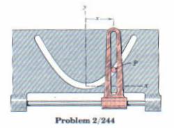
Problem
To facilitate the use of Adams, we will use the physical model shown below. The gray member is driven side to side with the displacement x = 45*sin(2*time). The red member is constrained to move up and down. A pin in the red member protrudes through a slot in the gray member. As the gray member translates, the red member is forced up and down. Your task it to plot the vertical displacement of the red member as a function of time.
![]()
Setting up the modeling environment.
- The grid spacing needs to be
reset to a higher resolution for this model.
Go to the Settings pull-down menu at the top of the ADAMS window and select Working Grid... - In the Spacing text
fields, enter 10mm under both X and Y.
Click OK. The spacing between grid points is now set to 10mm. You may even want to set the Y spacing at 1 mm. - Under the “view” menu, select the “coordinate window” option to display the cursor coordinates.
- Click on the Select icon.

The View Control panel appears in the Toolbox. - Click on the Dynamic Zoom
icon.

Now click and hold with the left mouse button anywhere inside the Modeling window. Move the mouse up to zoom in and move it down to zoom out.
Making the (gray) slot part.
- Click on the parts palette in
the Toolbox with the right mouse button.
The button stack for parts appears. - Click on the Spline icon
 with the left mouse button.
 - In the lower part of the
Toolbox, verify the text field is set to New Part.
Make sure that Closed is not selected.
4. Use about 8 points to define the curve y = (x*x) / 40. It is best if the apex of the parabola is at the origin. (This makes it easier to establish the point on curve constraint.)
5.
Use the Rigid Body: Box tool
![]() from the parts button stack to add a mass to
the slot. Make sure that in the New Part pull-down menu, you select
Add to Part.
from the parts button stack to add a mass to
the slot. Make sure that in the New Part pull-down menu, you select
Add to Part.
6.
Use the Joint:Translational icon
![]() to add a horizontal slider joint to the mass.
Make sure that the axis lies in the x-y plane. From the “view
menu, go the “pre-set” to view the model from other viewpoints to determine
if the joint is in the correct plane.
to add a horizontal slider joint to the mass.
Make sure that the axis lies in the x-y plane. From the “view
menu, go the “pre-set” to view the model from other viewpoints to determine
if the joint is in the correct plane.
7.
Use the translational joint motion source to drive the slider joint
![]() . Right click on the motion source, modify it, and change the displacement
function to 45*sin(2*time).
. Right click on the motion source, modify it, and change the displacement
function to 45*sin(2*time).
Making the (red) pin part.
1.
Use the Rigid Body: Box tool
![]() from the parts button stack to create a mass.
Make sure that in the New Part pull-down menu, you select New Part.
from the parts button stack to create a mass.
Make sure that in the New Part pull-down menu, you select New Part.
2.
Use the Joint:Translational icon
![]() to add a vertical slider joint to the mass.
Make sure that the axis lies in the x-y plane.
to add a vertical slider joint to the mass.
Make sure that the axis lies in the x-y plane.
3.
Use the Rigid Body: point tool
![]() to add a point to the mass. Make sure
that in the Add to Ground pull-down menu, you select Add to part.
Click on the mass to select it, then click to locate the point. The point
should be placed at the apex of the parabola.
to add a point to the mass. Make sure
that in the Add to Ground pull-down menu, you select Add to part.
Click on the mass to select it, then click to locate the point. The point
should be placed at the apex of the parabola.
4.
Use the Joint: Pin-in-slot tool
![]() to place a constraint between the
point and the curve representing the slot.
to place a constraint between the
point and the curve representing the slot.
After verifying the model, compute 10 seconds of simulation and plot the displacement of the pin. Submit a printout of the plot and a printout of your model. When printing the model, make sure that you are using the front view and that the simulation is reset to time=0 so that all of the joints and markers are visible.
Good luck!