1.1 360-Degree Render
Rendered a 360-degree view of a cow mesh using look_at_view_transform.

Cow orbiting 360 degrees.
By Teja Kanthamneni
Rendered a 360-degree view of a cow mesh using look_at_view_transform.
Recreated the Vertigo effect by modifying camera distance and FOV simultaneously.

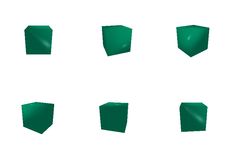
Constructed basic 3D shapes from scratch by manually defining vertices and faces, then applied a 360-degree rotation.

Retextured the cow mesh based on the relative Z-coordinate of each vertex to create a smooth color gradient across the cow mesh. Colors: Green [0, 0.7,0.5] to Purple [0.5, 0.2, 1]

Modified the relative rotation ($R_{rel}$) and translation ($T_{rel}$) to achieve four distinct camera viewpoints. ($R_{rel}$) rotates the camera from its initial configuration (inverse of how the mesh rotates). ($T_{rel}$) defines where the world origin is located relative to the camera.

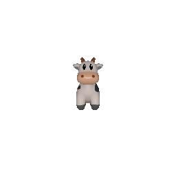
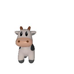

Unprojected RGB-D images into 3D point clouds, applying a coordinate flip to map them properly to PyTorch3D space.


Sampled continuous parametric equations to generate 3D point clouds.

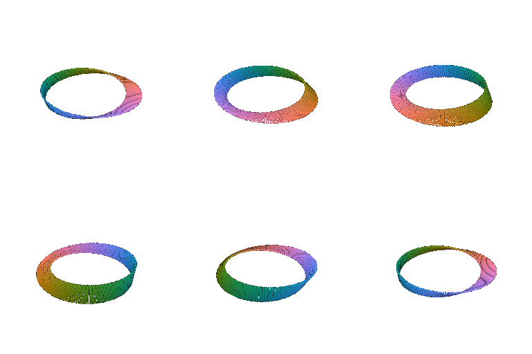
Utilized marching cubes to extract a mesh from an implicitly defined 3D voxel grid $F(x,y,z) = 0$.
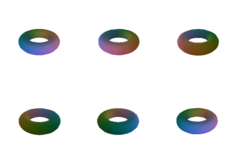

When selecting a 3D representation for rendering or processing, there are several key tradeoffs to consider:
| Criteria | Comparison Summary |
|---|---|
| Rendering Speed | Meshes are generally slower to render because they require rasterization, normal calculations, z-buffering, and shading algorithms. Point clouds are significantly faster since they only require projecting 3D coordinates onto the 2D screen. However, depending on the desired quality/fidelty of the rendering, a greater number of points may be required for a point cloud, which can make it slower than a mesh rendering. |
| Rendering Quality | Meshes provide higher rendering quality due to their continuous surfaces, support for lighting and smooth texturing. In contrast, point clouds have lower visual fidelity and can appear to have holes unless the point density is high. |
| Ease of Use | Point clouds are simpler to process and capture directly from hardware because they are unorganized, raw coordinates. Meshes are more complex to generate and manipulate due to their connectivity. |
| Memory Usage | Point clouds are generally more memory efficient as they only store a 3D coordinate and potentially a color, while meshes require the face connectivity matrix. However, to achieve similar quality renderings, meshes could end up using less memory as it can leverage its connectivity to fill in gaps. |
Implemented a linear interpolation algorithm to morph a parametric Torus point cloud into a Sphere over time.

Converted a 3D mesh into a point cloud by sampling faces proportionally to their area, then uniformly sampling barycentric coordinates using the square root trick to prevent vertex clustering.


