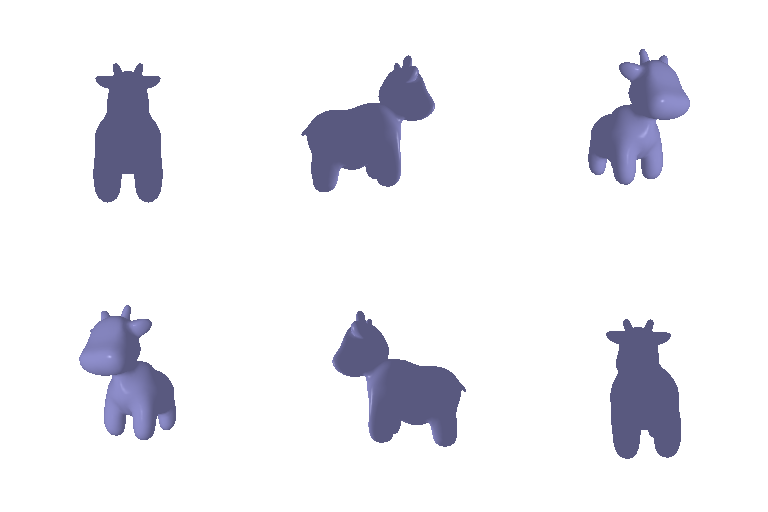

4. Camera Transformations
Untransformed image ($R=I_3$, $T=0_3$, corresponding to the 3D identity matrix & 3-entry zero vector):

For world coordinates, we can take +X, +Y, and +Z as leftward, upward, and away from the camera (toward the cow) in the original image, matching the rotation arrows drawn in the images.
(1) We want $T_1,\;R_1$ to encode how the world is transformed, relative to the camera. (We can then use these to compute coordinates in the camera frame, given coordinates in the world frame, i.e. $X_c=[R_1\;T_1]X_w$.)
Assuming a fixed camera (and that the world is somehow rotating around it, as seen in the cow), we see that after applying $R_1$, the transformed world's X direction (corresponding to the red arrow) is upward [+Y] in the camera's frame, i.e. $X_{out}=[0,1,0]\cdot XYZ_{in}$. This gives us the first row of our matrix. Similarly, we see that +Y, after transformation, is rightward [-X] in the camera's frame, i.e. $Y_{out}=[-1,0,0]\cdot XYZ_{in}$, yielding the second row of our matrix. In contrast, the Z axis is untransformed, hence $Z_{out}=[0,0,1]\cdot XYZ_{in}=Z_{in}$.
For the translation vector, since the cow is occupying the same position + has the same size as in the original image, we see that the camera's position hasn't changed, i.e. $T_1=0_3$.
$$R_1=\left(\begin{array}& 0 & 1 & 0 \\ -1 & 0 & 0 \\ 0 & 0 & 1\end{array}\right)\quad T_1 = [0, 0, 0]$$

(2) For the second image, the cow is smaller than previously, meaning that the camera has gotten farther away from the cow. Since the angle is the same as the original image, there's no translation on the X or Y axes, nor has the camera been rotated. Assuming a fixed camera, the world [the cow] has moved further away from the camera, corresponding to a positive translation by the world in the direction of the Z-axis.
$$R_2=\left(\begin{array}& 1 & 0 & 0 \\ 0 & 1 & 0 \\ 0 & 0 & 1\end{array}\right)\quad T_2 = [0, 0, 3]$$

(3) For the third image, we needed the camera to be offset from the cow. From the camera's perspective, the cow is further to the left than previously - assuming a fixed camera, the world [cow] has moved left, corresponding to a positive translation by the world in the direction of the X-axis.
When we do this translation, we find that the images match up even without any rotation, hence we can leave $R_3=I_3$.
$$R_3=\left(\begin{array}& 1 & 0 & 0 \\ 0 & 1 & 0 \\ 0 & 0 & 1\end{array}\right)\quad T_3 = [0.5, 0, 0]$$

(4) Following a similar process to (1), we see that +X in the world frame [away from the camera/toward the cow] now corresponds to +Z in the new camera frame, i.e. $X_{out}=[0,0,1]XYZ_{in}$. Upright, or +Y, is the same as in the original image, hence $Y_{out}=[0,1,0]\cdot XYZ_{in}$. Finally, +Z [the blue arrow facing rightward] corresponds to -X in the new camera frame, i.e. $Z_{out}=][-1,0,0]\cdot XYZ_{in}$.
Additionally, we also want our camera to be in a new position to the side of the cow (+3 in the Z axis of the rotated frame). As such, we need our translation $T_4$ to both (a) "undo" the original $[0,0,3]$ transformation (in the original frame), and (b) apply the new $[0,0,3]$ transformation in the rotated frame. The compensation we need for (a) is $-R_4[0,0,3]^T=[-3,0,0]$, which negates the original transformation; adding $[0,0,3]$ (our new transformation yields our final translation vector $T_4=[-3,0,3]$.
$$R_4=\left(\begin{array}& 0 & 0 & 1 \\ 0 & 1 & 0 \\ -1 & 0 & 0 \end{array}\right)\quad T_4 = [-3, 0, 3]$$

5. Rendering Generic 3D Representations
5.1 Rendering Point Clouds from RGB-D Images
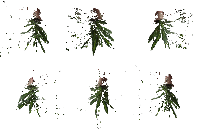
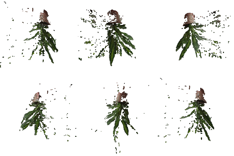
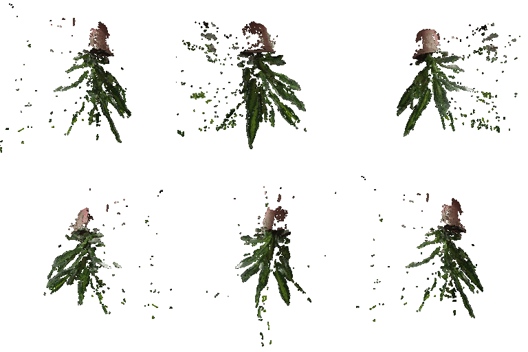
Corresponding to image 1, image 2, and union(image 1, image 2) & containing 125035, 125035, and 250070 points, respectively:
5.2 Parametric Functions
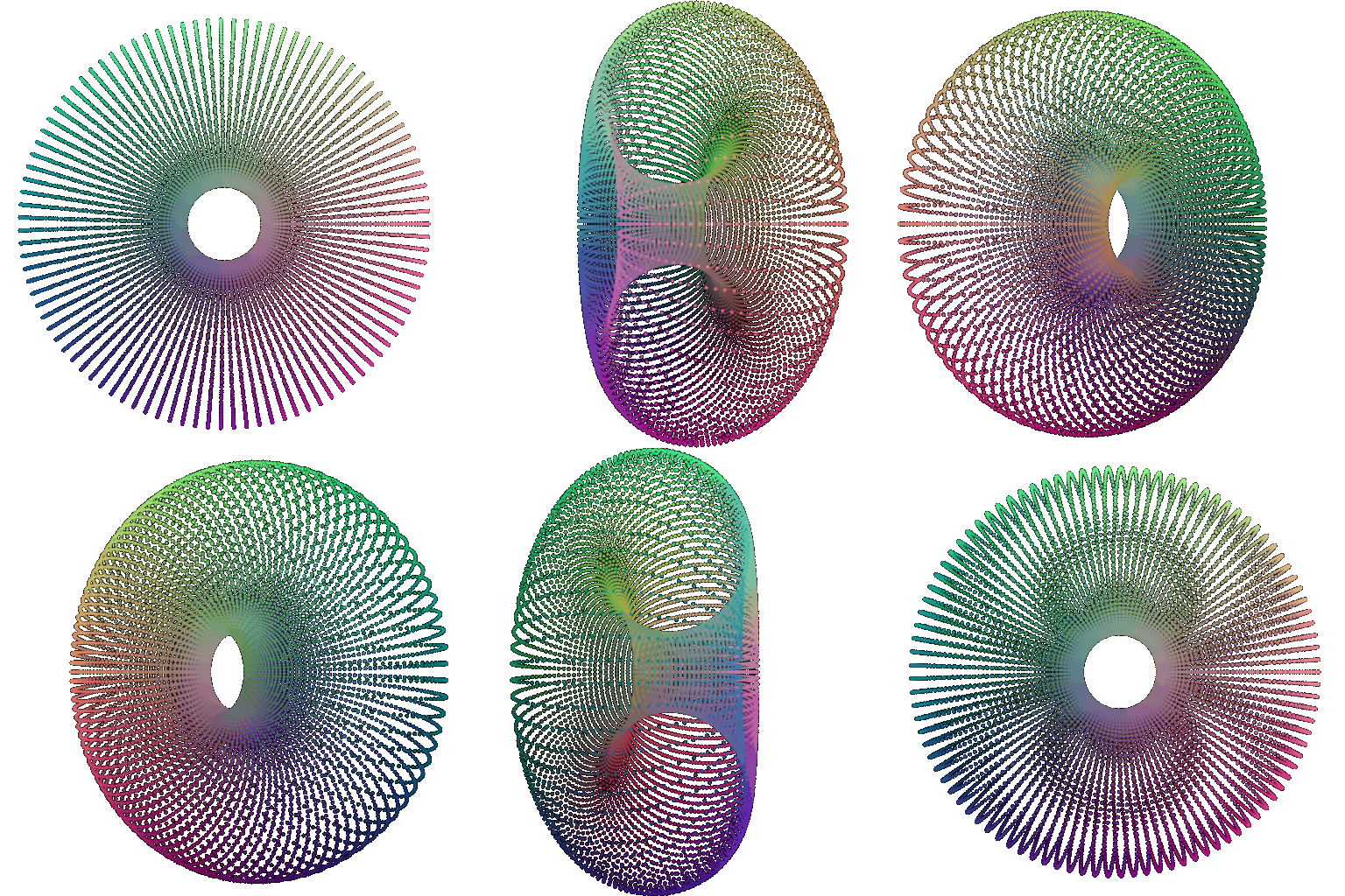
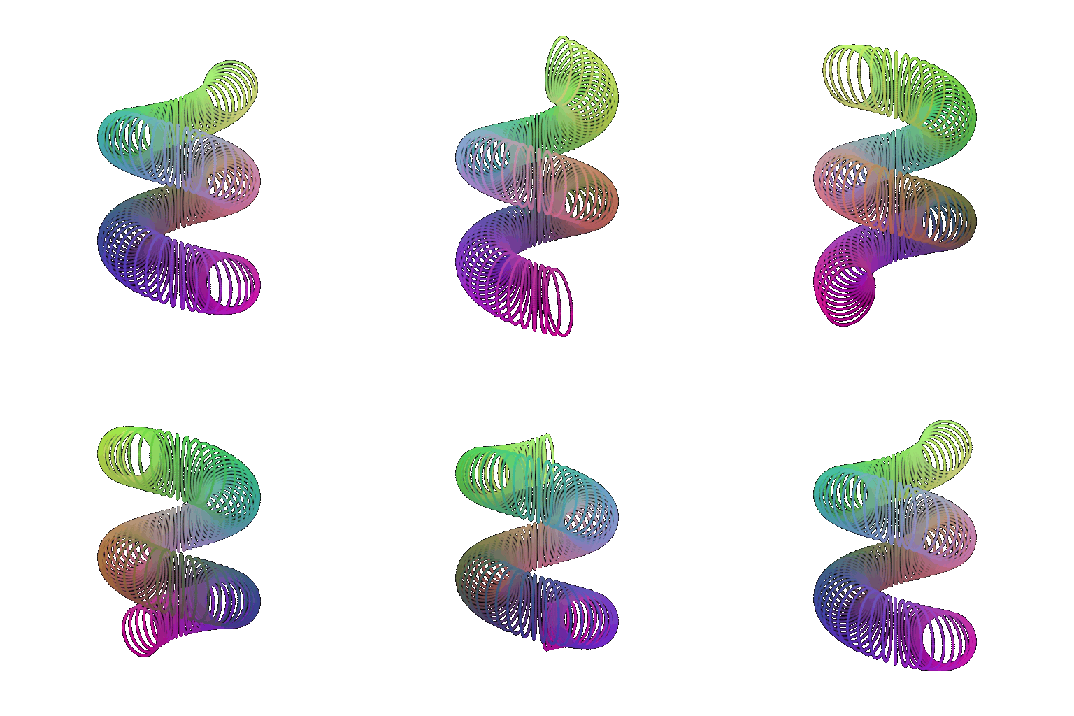
The sampling function for the torus is the standard one: given $\theta\in[0,2\pi)$ and $\phi\in[0,2\pi)$, and given major and minor radii $R_1$ and $R_2$, rsepectively:
$x=(R_1+R_2\sin\theta)\cos\phi$
$y=(R_1+R_2\sin\theta)\sin\phi$
$z=R_2\cos\theta$
For my non-torus object, I originally set out to do a snake, but ended up doing corkscrew macaroni pasta instead, where given $\theta\in[0,2\pi)$, $\phi\in[0, 4\pi)$, and major & minor radii $R_1,R_2$:
$x=(R_1+R_2\cos\theta)\cos\phi$
$y=(R_1+R_2\cos\theta)\sin\phi$
$z=R_2\sin\theta+0.3\phi$
5.3 Implicit Surfaces
Given major & minor radii $R_1,R_2$, we can obtain a torus via the implicit function:
$$f(x,y,z)=\left(\sqrt{x^2+y^2}-R_1^2\right)^2+z^2-R_2^2$$
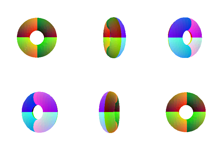
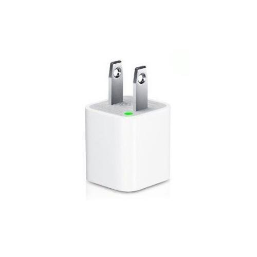
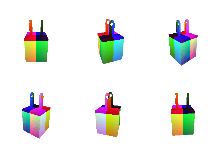
For my other object, I did the USB-A charging block I use for my phone (pictured below), minus the tapered edges. I did this via a combination of 3 different functions (defining True = 1 and False = -1 for boolean values):
- $f_1(x,y,z)=(x>-0.5)\;\&\&\;(x<0.5)\;\&\&\;(y>-1.1)\;\&\&\;(y<0.1)\;\&\&\;(z>-0.5)\;\&\&\;(z<0.5)$
- $f_2(x,y,z)=-50|z|(y-0.5)+\big[\left\{(x>-0.3)\;\&\&\;(x<-0.2)\right\}\;||\;\left\{(x>0.2)\;\&\&\;(x<0.3)\right\}\big]\;\&\&\;(y>-0.1)\;\&\&\;(y<0.8)\;\&\&\;(z>-0.12)\;\&\&\;(z<0.12)$
- $f_3(x,y,z)=0.07-\sqrt{z^2+(y-0.6)^2}$
These 3 functions correspond to the base, prongs, and prong cutouts, respectively. The overall implicit function was thus:
$$f(x,y,z)=\max[f_1,\min(f_2,-f_3)]$$
Comparing mesh vs. point cloud representations:
- Meshes explicitly encode connectivity info (and possibly normal directions as well), whereas point clouds don't -- for visualization purposes, this makes meshes both more visually interpretable and readily texturable, whereas the same cannot necessarily be said for point clouds.
- Point cloud representations can tend to require more points to "properly" represent a surface (from a visual standpoint) compared to a mesh, which may result in a higher memory footprint and slower rendering speed on the part of the point cloud. However, meshes can fall apart at very low point counts in ways that point clouds might not, at least not to the same degree.
- If 3D data is given in point cloud format, as is often the case, then the requisite surface reconstruction needed to obtain a mesh is both potentially expensive and error-prone (depending on the geometry). There are also other kinds of representations (e.g. depth image) that are more easily made into point clouds than into meshes.
- The point cloud format itself is simpler and more straightforward than the various mesh formats (e.g. less information is encoded, no need to worry about orderings, etc.).
(Extra Credit) 6. Do Something Fun
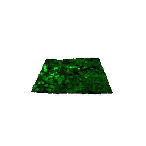
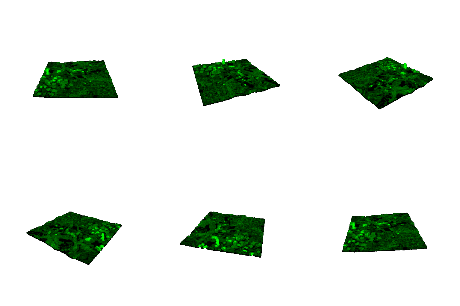
For this part of the assignment, I downloaded (& subsampled) an aerial LiDAR scan of the general CMU area from the USGS National Map, sourced in point cloud format. This particular scan had classification labels for each point; notably, all ground points were grouped under a single label. Using this information, I was able to construct a rough digital terrain model (DTM) of the ground as a 2D grid, where the ground elevation in each 100yd x 100yd cell was simply the minimum Z coordinate among all ground points falling in that cell. (A few cells didn't contain any ground points, in which case I left them as zero. Ideally you'd do some kind of interpolation, but the output looked okay enough such that I didn't feel the need.)
I was then able to use this to assign an elevation value to each non-ground point in the point cloud, given as max(0, point Z coordinate - ground elevation) [where ground elevation was the grid value for whichever cell the non-ground point fell into]. The coloring of non-ground points in the final output is thus determined by elevation (where higher elevation = brighter), with all ground points being colored black.
(Extra Credit) 7. Sampling Points on Meshes
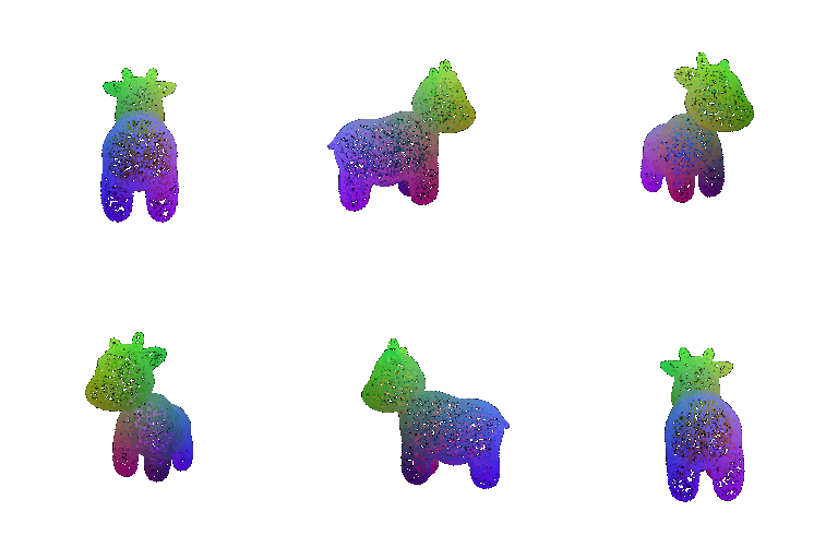
Original mesh:
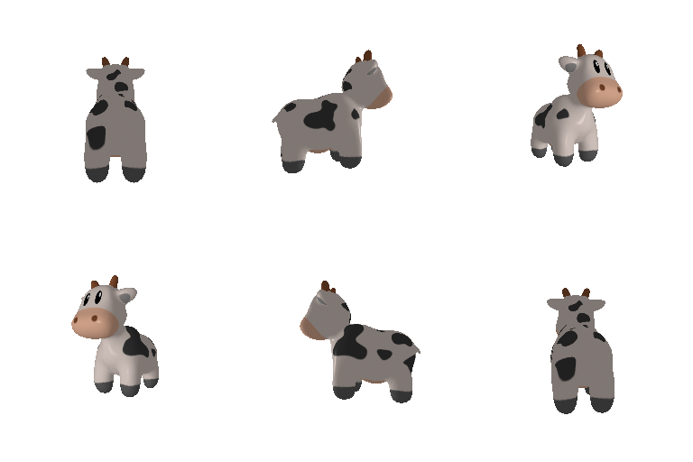
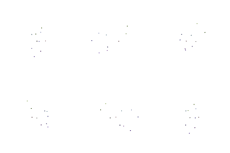
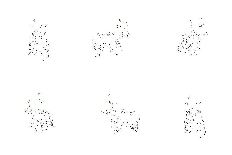
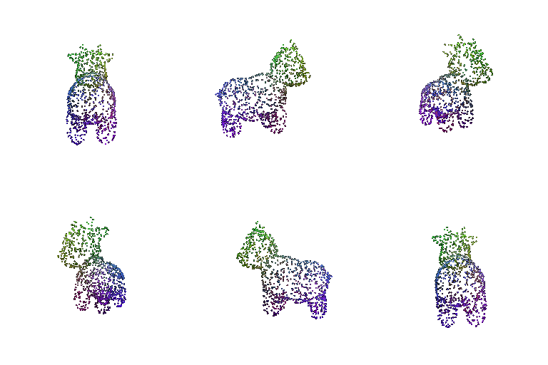
Comparing to samples of 10, 100, 1000, and 10000 points, respectively: