16-825 Assignment 1: Rendering Basics with PyTorch3D
Name: Ruinian (Ray) Xue
AndrewID: ruinianx
Goals: In this assignment, you will learn the basics of rendering with PyTorch3D, explore 3D representations, and practice constructing simple geometry.
You may also find it helpful to follow the Pytorch3D tutorials.
Table of Contents
Practicing with Cameras (15 Points)
Practicing with Meshes (10 Points)
Re-texturing a mesh (10 Points)
Camera Transformations (10 Points)
Rendering Generic 3D Representations (45 Points)
Do Something Fun (+10 Extra Credit)
1. Practicing with Cameras (15 Points)
1.1. 360-degree Renders (5 points)
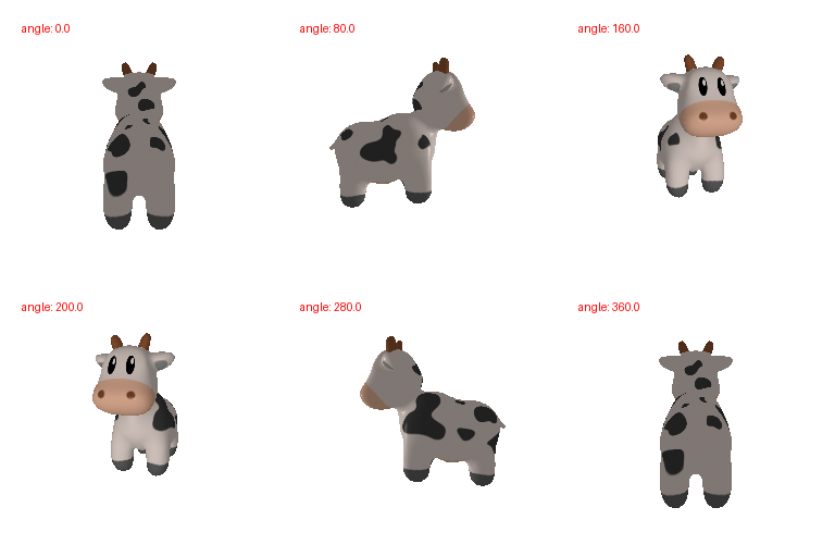
Your first task is to create a 360-degree gif video that shows many continuous views of the provided cow mesh. For many of your results this semester, you will be expected to show full turntable views of your outputs. You may find the following helpful:
1.2 Re-creating the Dolly Zoom (10 points)
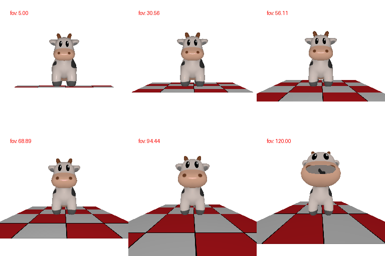
The Dolly Zoom is a famous camera effect, first used in the Alfred Hitchcock film Vertigo. The core idea is to change the focal length of the camera while moving the camera in a way such that the subject is the same size in the frame, producing a rather unsettling effect.
2. Practicing with Meshes (10 Points)
2.1 Constructing a Tetrahedron (5 points)
In this part, you will practice working with the geometry of 3D meshes. Construct a tetrahedron mesh and then render it from multiple viewpoints. Your tetrahedron does not need to be a regular tetrahedron (i.e. not all faces need to be equilateral triangles) as long as it is obvious from the renderings that the shape is a tetrahedron.
Number of Vertices: 4
Number of Faces: 4

2.2 Constructing a Cube (5 points)
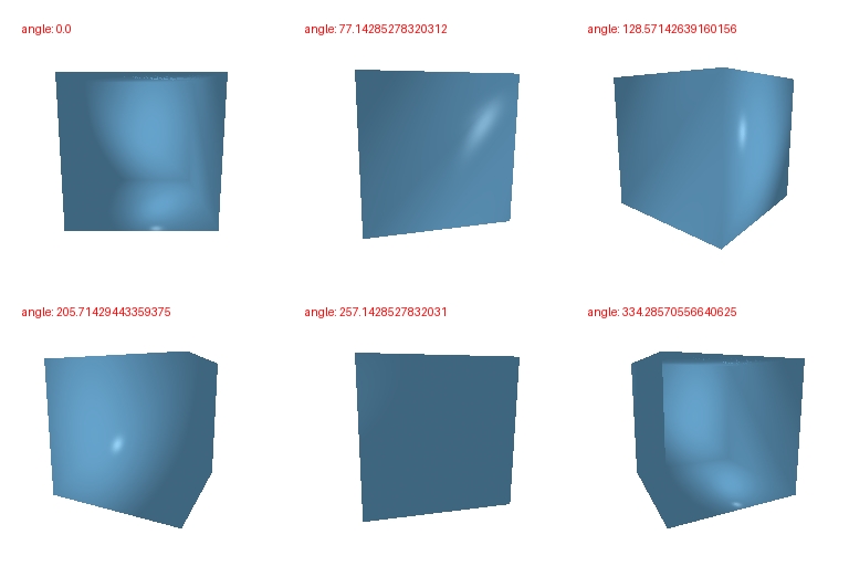
Construct a cube mesh and then render it from multiple viewpoints. Remember that we are still working with triangle meshes, so you will need to use two sets of triangle faces to represent one face of the cube.
Number of Vertices: 8
Number of Faces: 12
3. Re-texturing a mesh (10 points)
Now let's practice re-texturing a mesh. For this task, we will be retexturing the cow mesh such that the color smoothly changes from the front of the cow to the back of the cow.
Choice of color1 and color2: use normal color picker for hex code of colors, I notice in Microsoft Excel we can easily choose color (is quicker than opening Adobe Photoshop) and get both hex code and RGB number. Then we can divide it into 255.
color1 = [1,0.67,0.82] #pinkcolor2 = [0.52,0.79,0.96] #blue

4. Camera Transformations (10 points)
When working with 3D, finding a reasonable camera pose is often the first step to producing a useful visualization, and an important first step toward debugging.
Running
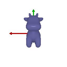
python -m starter.camera_transformsproduces the following image using the camera extrinsics rotationR_0and translationT_0:
Overall explanation (base idea)
First, evaluate the difference between the formula in class and the formula in pytorch3d.
We have pytorch3d.renderer.FoVPerspectiveCameras are right-multiplied by
In the code, we have
Given the fact that
What's more, the T in the code, is the result of
Howerver, we cannot simply equal
Transform 1: Rotate Camera Counterclockwise
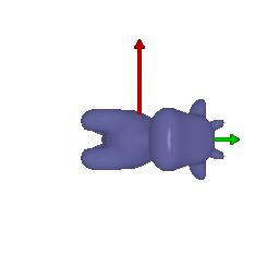
Based on the overall explanation above, in this case, we only rotate the camera counterclockwise, not affecting the camera position in the world coordinate system.
So the
For the rotation, we changed from
But the
Thus,
In this case,
Transform 2 : Move Camera Further Back
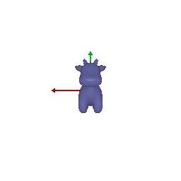
Based on the overall explanation above, in this case, we only move the camera further away, not rotating the camera coordinate system.
So the
Because the
As we move it further back along the -z axis, with the z-axis, I chose it to be
So the parameter to fill in this case is:
Transform 3: Shift Camera to the right
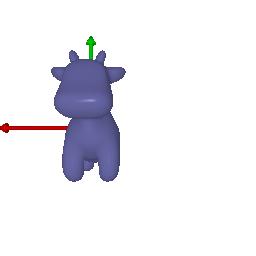
Similar to transform 3, we don't need to rotate the camera and the
So the parameter to fill in this case is:
Transform 4:Move Camera to the Right Side
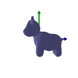
This is a somewhat more complicated case, and due to the complexity of the formula in the code, based on the right-multiplation in PyTorch3D, I try to prove and make conclusion for the calculation of
Conclusions on the camera and world based on lecture:
Based on
based on 1, we know
After the rotation, without moving the camera, we cannot capture any photo of the cow, because the
z-axisof the camera is not facing the cow, so we need to move the camera. Define the movement of camera after rotation, based on camera coordinate system,Assuming world not move so we can get
Digging it further, we can find it out that geometrically,
based on 10&11,
And this is the geometrical meaning of T_relative, I got it right. But I really wonder what this T - R_relative @T_0, that's correct, but I really want to figure out why it equals
In summary,
And,
5. Rendering Generic 3D Representations (45 Points)
The simplest possible 3D representation is simply a collection of 3D points, each possibly associated with a color feature. PyTorch3D provides functionality for rendering point clouds.
5.1 Rendering Point Clouds from RGB-D Images (10 points)
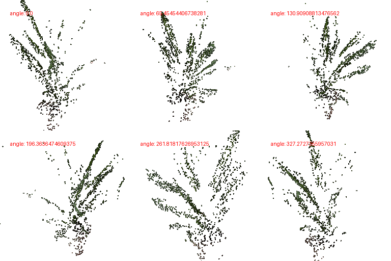
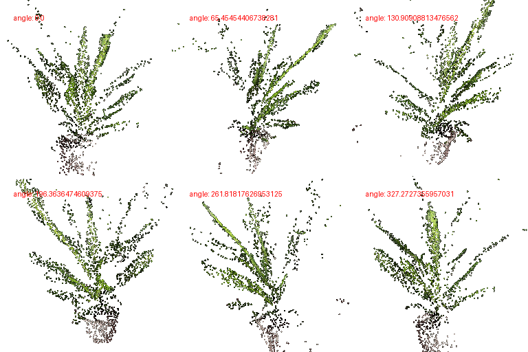
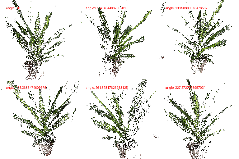
In this part, we will practice rendering point clouds constructed from 2 RGB-D images from the Common Objects in 3D Dataset.
In
render_generic.py, theload_rgbd_datafunction will load the data for 2 images of the same plant. The dictionary should contain the RGB image, a depth map, a mask, and a Pytorch3D camera corresponding to the pose that the image was taken from.You should use the
unproject_depth_imagefunction inutils.pyto convert a depth image into a point cloud (parameterized as a set of 3D coordinates and corresponding color values). Theunproject_depth_imagefunction uses the camera intrinsics and extrinisics to cast a ray from every pixel in the image into world coordinates space. The ray's final distance is the depth value at that pixel, and the color of each point can be determined from the corresponding image pixel.
Construct 3 different point clouds side by side:
5.2 Parametric Functions (10 + 5 points)
A parametric function generates a 3D point for each point in the source domain. For example, given an elevation
thetaand azimuthphi, we can parameterize the surface of a unit sphere as(sin(theta) * cos(phi), cos(theta), sin(theta) * sin(phi)).By sampling values of
thetaandphi, we can generate a sphere point cloud.
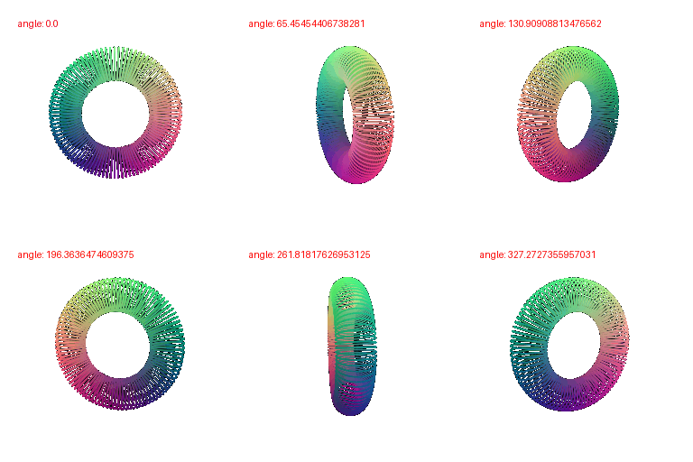
Render a torus point cloud
Your task is to render a torus point cloud by sampling its parametric function.
According to Wikipedia:
A new object of my chioce
I chose to draw a heart using the parameter equation online.
Equation credit from: Mathmetics-Parametric equation for Taubin heart surface
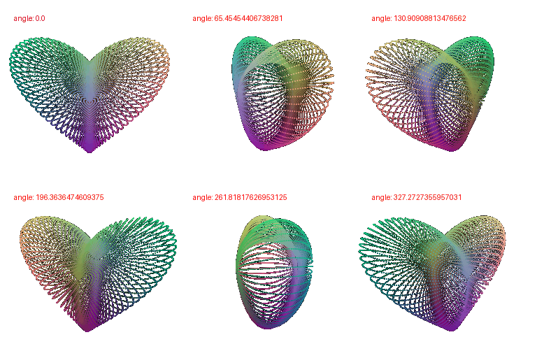
After using the parameter equation, I found out the heart rotates facing strangely, so I swapped the points in z-axis and y-axis:
xxxxxxxxxx points = torch.stack((x.flatten(), z.flatten(), y.flatten()), dim=1)5.3 Implicit Surfaces (15 + 5 points)
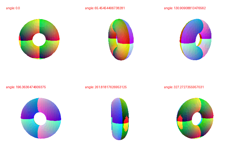
In this part, we will explore representing geometry as a function in the form of an implicit function. In general, given a function F(x, y, z), we can define the surface to be the zero level-set of F i.e. (x,y,z) such that F(x, y, z) = 0. The function F can be a mathematical equation or even a neural network. To visualize such a representation, we can discretize the 3D space and evaluate the implicit function, storing the values in a voxel grid. Finally, to recover the mesh, we can run the marching cubes algorithm to extract the 0-level set.
Torus mesh
Tradeoff between mesh and point cloud
Rendering speed: In our case, the plants has really less points, so the rendering speed is really fast. But if the points get more, in the parameter funtion vs implicit surface case, for the same object, the point clouds take more time to render.
Rendering quality: Mesh has better overall quality, especially when using implicit surfaces for sampling. Comparing parameter function using point cloud and implicit surfaces using mesh, meshes are smoother and have less noise. Point clouds has really explicit points especially when there are less points, and they are not really affected by lights.
Ease of use: Point clouds are easier to use, in fewerm lines of codes can we render them. For meshes, we need to indicate vertices and faces.
Memory usage: Representing point cloud needs more memory, but rendering complicated meshes needs a big amount of memory. Especially in my following case for extra point, the Loomis Model I downloaded from internet has much more vertices and faces and it takes time and memory to load and render. So we cannot simply say which one exactly uses more, it depends on the quality.
Summary: Meshes has better quality but sometimes are limited in shape and implement (more difficult to implement), point clouds has more flexibility but not really interactive to lights and look not smooth, and if points get more, it costs to compute and render.
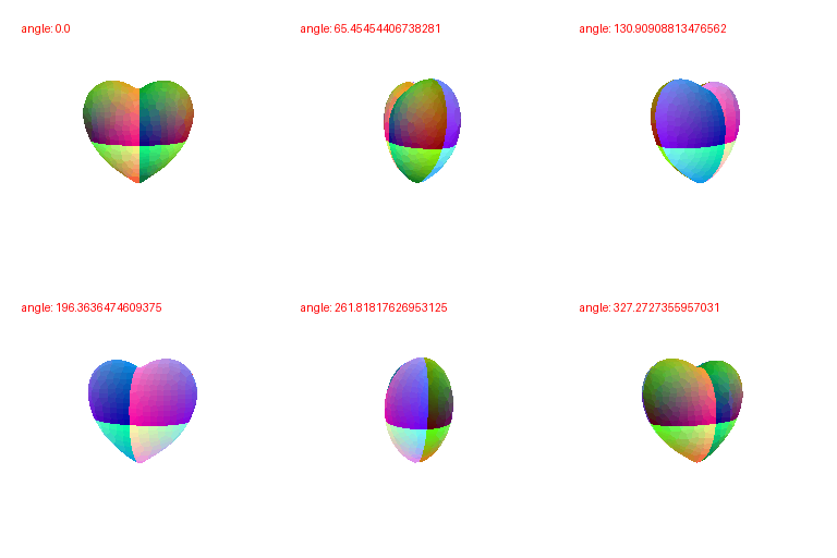
Render the heart again
According to the reference link above, the heart implicit function is:
Thus we can put it in the code, and the result is listed below:
(Extra Credit) 6. Do Something Fun (+10 points)
Now that you have learned to work with various 3D represenations and render them, it is time to try something fun. Create your own 3D structures, or render something in an interesting way, or creatively texture, or anything else that appeals to you - the (3D) world is your oyster! If you wish to download additional meshes, Free3D is a good place to start.
During the past summer, I learned Loomis Model in manually drawing human head, when drawing a human head in mangas, we need to know about the strcuture of the head, and Loomis Model is a really interesting and simple sample to do this.

So I downloaded a .glb document from sketchfab and converted it into meshes using trimesh, after that, I tried to make it shining, rotating with different light, which is funny, looks like meme. So I changed the light and angle within every frame, and make the color from pink to blue (the same in the bi-color cow).