Assignment 1: Rendering Basics with PyTorch3D
1. Practicing with Cameras
1.1 360-degree Render

1.2 Dolly Zoom

2. Practicing with Meshes
2.1 Tetrahedron
The tetrahedron mesh has 4 vertices and 4 triangular faces.

2.2 Cube
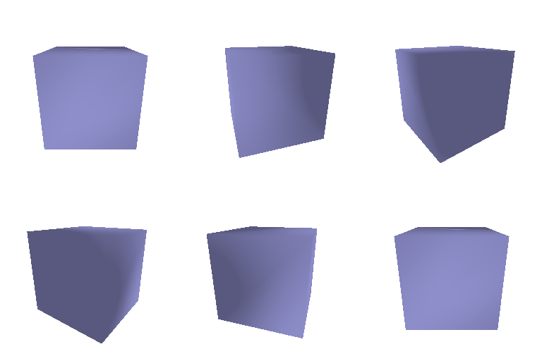
The cube mesh has 8 vertices and 12 triangular faces. Each square face is represented using two triangles.
3. Re-texturing a Mesh
I used a bright mint green color "#07f49e" for the front of the cow and a deep purple color for the back "#42047e".

In normalized RGB, these are approximately:
color1 = [0.027, 0.957, 0.620]
color2 = [0.259, 0.016, 0.494]
Each vertex color is linearly interpolated by its z-coordinate:
alpha = (z - z_min) / (z_max - z_min)
color = alpha * color2 + (1 - alpha) * color1
4. Camera Transformations
Transform 1
| Target | My Result |
|---|---|
 |
 |
This transformation rotates the camera view around the z-axis, so the cow appears rotated in the image plane.
R_relative = [
    [0,  1, 0],
    [-1, 0, 0],
    [0,  0, 1],
]
T_relative = [0, 0, 0]
Transform 2
| Target | My Result |
|---|---|
 |
 |
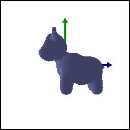
This transformation rotates the camera around the y-axis and translates it so the cow is viewed from the side.
R_relative = [
    [0, 0,  1],
    [0, 1,  0],
    [-1, 0, 0],
]
T_relative = [-3, 0, 3]
Transform 3
| Target | My Result |
|---|---|
 |
 |
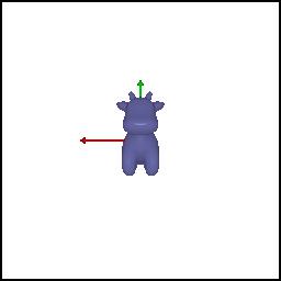
This transformation moves the camera farther away from the cow, making the rendered cow appear smaller.
R_relative = [
    [1, 0, 0],
    [0, 1, 0],
    [0, 0, 1],
]
T_relative = [0, 0, 3]
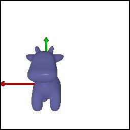
Transform 4
| Target | My Result |
|---|---|
 |
 |
This transformation shifts the camera view so the cow appears lower and more to the left in the rendered image.
R_relative = [
    [1, 0, 0],
    [0, 1, 0],
    [0, 0, 1],
]
T_relative = [0.4, -0.4, 0]
5. Rendering Generic 3D Representations
5.1 Point Clouds from RGB-D Images
The gif shows the point cloud from the first RGB-D image, the point cloud from the second RGB-D image, and the union of both point clouds side-by-side.

5.2 Parametric Functions
Torus Point Cloud
The torus point cloud was generated by sampling the parametric surface
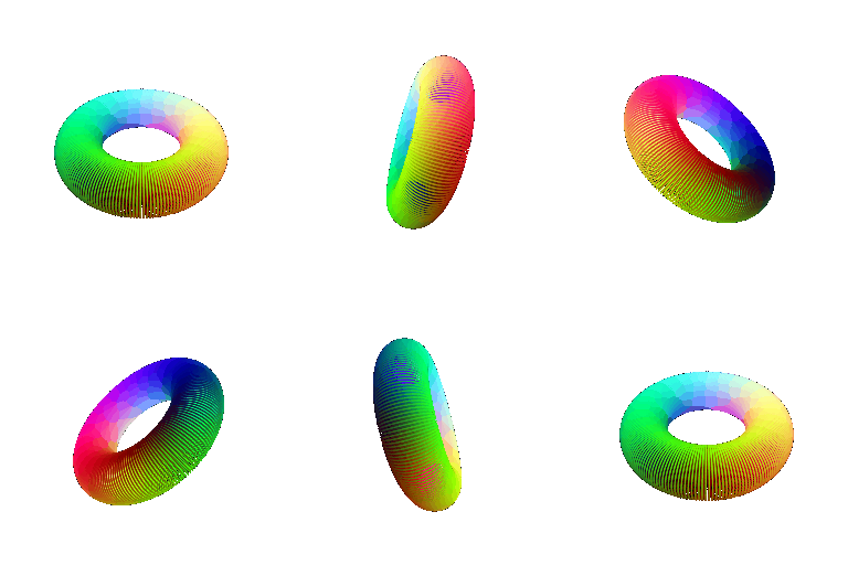
x = (R + r * cos(v)) * cos(u)
y = (R + r * cos(v)) * sin(u)
z = r * sin(v)
Twisted Torus Point Cloud
For the extra parametric object, I rendered a twisted torus by modulating the minor radius as a function of the angular parameters.

5.3 Implicit Surfaces
Torus Mesh

The torus mesh was generated from the implicit function
F(x, y, z) = (sqrt(x^2 + y^2) - R)^2 + z^2 - r^2and extracted with marching cubes.
Mesh vs Point Cloud Tradeoffs
Point clouds are easy to construct and render directly from sampled data, RGB-D images, or parametric equations. They are flexible, but sparse point clouds can look noisy or incomplete, and the visual quality depends heavily on sampling density and point radius.
Meshes usually give cleaner surfaces because triangle faces explicitly define connectivity. They support smoother shading and more continuous silhouettes, but they require face information or an extraction method such as marching cubes. Mesh generation can also be more expensive in memory and computation, especially for high-resolution implicit surfaces.
Metaballs Mesh

For the extra implicit object, I rendered metaballs using a scalar field formed by two radial functions:
F(x, y, z) = sum(radius_i^2 / distance_i^2) - thresholdThe zero level set produces a smooth fused surface between the two blobs.
6. Do Something Fun
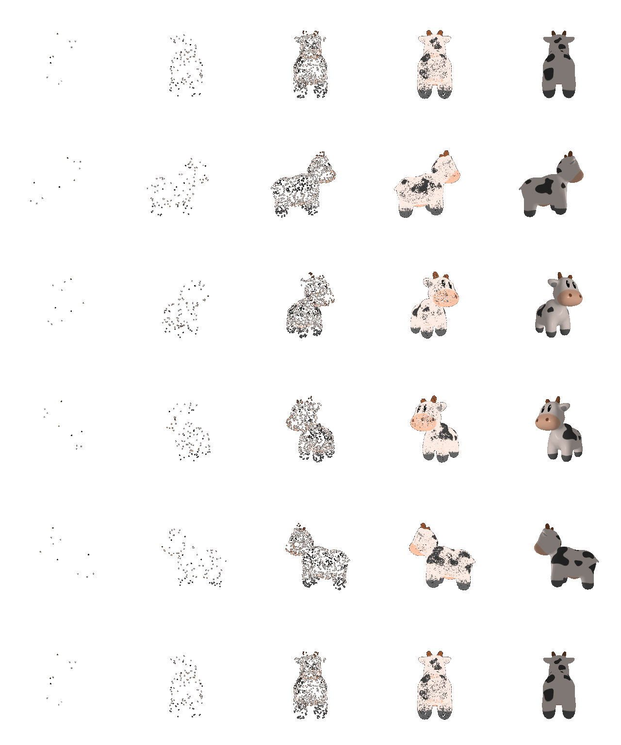
For the creative extra credit, I animated an implicit metaball surface. The two metaballs move apart, merge into one connected surface, and then separate again. Each frame is generated by evaluating a new implicit field, extracting the zero level set with marching cubes, and rendering the resulting mesh.

7. Sampling Points on Meshes
I sampled points from the cow mesh surface by selecting triangle faces with probability proportional to face area, then sampling barycentric coordinates uniformly within the selected face. The gif shows 10, 100, 1000, and 10000 sampled points, followed by the original cow mesh on the right.