Assignment 3: Neural Volume Rendering and Surface Rendering
By Lamia AlSalloom (lalsallo)
A. Neural Volume Rendering (80 points)
0. Transmittance Calculation (10 points)
We include our calculations in transmittance_calculation/a3_transmittance.pdf as well

1. Differentiable Volume Rendering
1.3. Ray Sampling (5 pts)
!python volume_rendering_main.py --config-name=box
TA Output (Grid)

Our Output (Grid)

TA Output (Rays)

Our Output (Rays)

1.4. Point Sampling (5 pts)
We implemented the StratifiedSampler.forward function to uniformly sample points
along each ray between the near and far bounds.
The visualization below shows our sampled points compared side by side with the TA’s output.
TA Output

Our Output

1.5. Volume Rendering (20 pts)
We implemented the _compute_weights and _aggregate functions in
VolumeRenderer to perform differentiable volume rendering.
This involves computing transmittance weights and aggregating
the sampled colors and densities to render both RGB and depth outputs.
We compare our results to the TA’s output for both rendered color and depth maps:
TA Output (Rendered Color)

Our Output (Rendered Color)

TA Output (Depth)

Our Output (Inferno Depth :)

2. Optimizing a basic implicit volume
2.1. Random ray sampling (5 pts)
We implement get_random_pixels_from_image in ray_utils.pylike this:

2.2. Loss and Training (5 pts)
We replaced the loss in train() with mean squared error (MSE)
between the predicted RGB values and the ground truth pixel colors rgb_gt.
We then trained the model using random ray sampling from 2.1.
!python volume_rendering_main.py --config-name=train_box
After training, we report the optimized box parameters (rounded to 1/100):
Box center: (0.25, 0.25, -0.00)
		  Box side lengths: (2.01, 1.50, 1.50)
These values come from the training log:
Box center: (0.250227153301239, 0.2505815625190735, -0.00044644795707426965)
		  Box side lengths: (2.0051045417785645, 1.5035862922668457, 1.5033165216445923)
2.3. Visualization
Below we compare our output after training to the TA’s output:
TA Output

Our Output

Before Training
Top Row: TA Results (Blue Border) | Bottom Row: Our Results (Purple Border)


After Training
Top Row: TA Results (Blue Border) | Bottom Row: Our Results (Purple Border)


3. Optimizing a Neural Radiance Field (NeRF) (20 points)
We implemented a Neural Radiance Field by defining NeuralRadianceField in implicit.py.
Our MLP maps 3D positions to both volume density and color.
The network uses ReLU activation to ensure non-negative density values and Sigmoid activation to map the remaining outputs to RGB color.
To improve representational quality, we also applied HarmonicEmbedding for positional encoding.
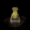
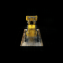
The results we have show a NeRF MLP that does not yet incorporate view dependence. It was trained for 250 epochs on 128×128 images from the Lego dataset.
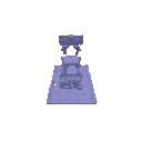
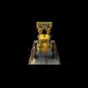
!python volume_rendering_main.py --config-name=nerf_lego
TA NeRF Render

Our NeRF Render

4. NeRF Extras
4.1 View Dependence
We extended our NeRF to include view dependent radiance, allowing emitted color to vary with the ray’s viewing direction. The MLP now takes both 3D position and encoded view direction as inputs. Density is predicted purely from position, while color depends on both position and view direction.
This modification results in more realistic renderings, especially for materials that exhibit specular reflections or view dependent highlights.
We use the nerf_materials scene to show this effect, where metallic and glossy surfaces now reflect light differently depending on the camera angle.
Our View Dependent NeRF (materials scene)

However, increased view dependence can reduce generalization if the training set lacks diverse viewpoints. In small datasets, the network might memorize appearance from specific angles, leading to overfitting. To balance realism and robustness, a large and varied dataset and a regularized architecture are important.
B. Neural Surface Rendering (50 points)
5. Sphere Tracing (10 points)
In this part, we implemented sphere_tracing in renderer.py to render implicit surfaces
from a signed distance function (SDF). The method iteratively marches along each ray by the distance predicted
by the SDF at the current point, efficiently converging to the surface intersection.
Description of the Algorithm
The sphere tracing algorithm starts at the ray origin and moves along the ray direction in steps proportional to the signed distance at the current point. Each step brings the point closer to the surface while making sure we do not overshoot it.
At every iteration, the new point is computed as the current point plus the distance to the nearest surface
multiplied by the ray direction. A mask is maintained with the same batch dimension as the ray origins to mark
which rays have already reached the surface, those with distances below 1e-6. The loop terminates once
all rays have converged or the maximum number of iterations has been reached.
!python -m surface_rendering_main --config-name=torus_surface
We compare our result to the TA output.
TA Output

Our Output

6. Optimizing a Neural SDF (15 points)
Eikonal Loss:
torch.mean(torch.square(torch.norm(gradients, dim=1, keepdim=True) - 1))
MLP Architecture:
- Harmonic embedding applied to input 3D points
- 7 fully connected layers with ReLU activation on all but the final layer
- A skip connection at the 4th layer to preserve spatial detail
!python -m surface_rendering_main --config-name=points_surface
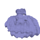
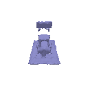
We compare our results with the TA’s reference.
TA Input Point Cloud

TA Reconstruction

Our Input Point Cloud

Our Reconstruction

7. VolSDF (15 points)
7. VolSDF
In this part, we extended the neural surface model to predict both color and density following the VolSDF formulation.
We implemented sdf_to_density to convert signed distance values into volumetric densities and trained the model on the bulldozer dataset.
Parameter intuition:
- Alpha (α): scales the overall density. A higher α makes the volume more opaque and helps rays terminate faster.
- Beta (β): controls the sharpness of the density transition around the surface. It determines how quickly the density changes near the SDF boundary.
1. How does high β bias your learned SDF? What about low β?
A higher β makes the density vary more smoothly across space, which spreads the transition region near the surface and produces softer or slightly blurred renderings. A lower β causes the density to change abruptly around the surface, creating sharper geometry and more distinct edges. However, very high β values can help produce smoother lighting and reflections, while very low β values may make training unstable if gradients become too localized.
2. Would an SDF be easier to train with volume rendering and low β or high β? Why?
It is easier to train with a higher β. When β is high, the SDF changes gradually, which provides smoother gradients that make optimization more stable. With a low β, gradients exist only in a narrow region near the surface, so training can become noisy and convergence slower.
3. Would you be more likely to learn an accurate surface with high β or low β? Why?
A lower β tends to produce a more accurate surface, since the transition is sharper and the model can capture finer geometric details. High β smooths out boundaries and can blur fine structures, though it often improves color smoothness and lighting consistency. In practice, a moderate β provides the best trade-off between stability and surface accuracy.
Hyperparameter tuning
We experimented with different β values while keeping α = 10. The best results were obtained with β = 0.05, it produced clear, well defined geometry without losing smooth shading. When β was too large, the surfaces became overly smooth, and when α was too small, the model failed to capture fine boundaries.
α = 10, β = 0.01

α = 10, β = 0.01

α = 10, β = 0.05

α = 10, β = 0.05

α = 10, β = 0.1

α = 10, β = 0.1

We then varied α while fixing β = 0.05. The optimal value was α = 25, which preserved surface sharpness while keeping rendering stable.
α = 1, β = 0.05
α = 1, β = 0.05
α = 25, β = 0.05
α = 25, β = 0.05
α = 50, β = 0.05
α = 50, β = 0.05
8. Neural Surface Extras
8.1 Render a Large Scene with Sphere Tracing
In this part, we extended our sphere tracing implementation to render a larger scene made up of many primitives. Instead of tracing a single torus as in Part 5, we instantiated over twenty analytic SDF shapes (mainly spheres and tori) at different positions and scales to form a composite implicit scene. Each primitive contributes its own signed distance field, and the overall scene SDF is defined as the pointwise minimum of all of them.
The same sphere_tracing function was reused, with only the scene definition updated.
This demonstrates how sphere tracing can efficiently handle multiple objects in a single implicit representation while maintaining smooth, continuous surfaces.
Rendered Multi-Sphere Scene

8.2 Fewer Training Views (EC)
For this experiment, we modified train_idx in dataset.py to reduce the number of training views.
We tested with 20, 10, and 5 views to evaluate how well NeRF and VolSDF generalize under limited supervision.
From the results, NeRF generally produces more detailed and accurate reconstructions when sufficient views are available. However, with very few views, VolSDF maintains more consistent geometry and smoother surfaces thanks to its implicit surface regularization.
20 Views
Left: Mesh representation | Middle: NeRF | Right: VolSDF
Mesh

NeRF

VolSDF

10 Views
Left: Mesh representation | Middle: NeRF | Right: VolSDF
Mesh

NeRF

VolSDF

5 Views
Left: Mesh representation | Middle: NeRF | Right: VolSDF
Mesh

NeRF

VolSDF
