How do a collection of 2D images become a coherent 3D scene? This project builds the geometry pipeline first, then trains two small multi-view transformers to render unseen views and predict scene geometry.
224 train · 28 val · 28 testFrom pixels to rays
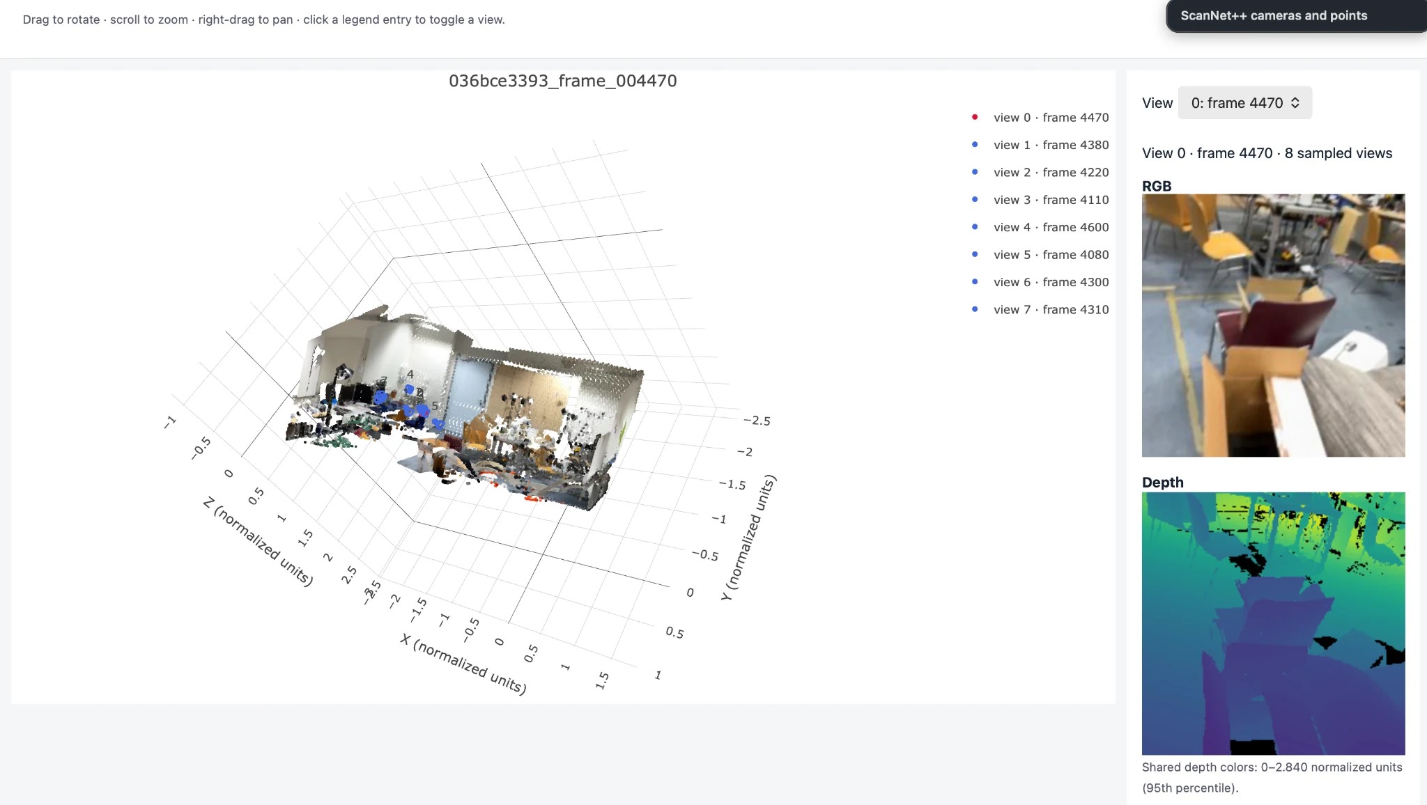
Each sampled clip is expressed in a shared coordinate frame. Depth unprojection lifts the pixels into 3D; canonicalization anchors the first camera and normalizes the scene scale.

Canonical coordinates
Camera-to-world poses are transformed into camera 0's frame. Camera translations, optical-axis depth and 3D points are divided by the distance from the origin to the valid-point centroid. The centroid itself is not subtracted.
Ray representation
For each pixel, the inverse intrinsic matrix gives a camera-space direction. Rotating it by the camera-to-world rotation and normalizing gives a unit world-space direction. Plücker coordinates store this direction and the moment of the ray.
Four sampled training clips passed the provided data check. Largest point reprojection error: 0.0001231 px; largest ray reprojection error: 0.0001079 px. Centroid distance: 1.0 for each clip.
Full data check
The complete output contains the four sample-level checks and batch shapes.
Canonicalization check · 036bce3393_frame_004470
For the scene shown above, camera 0 is at the origin to numerical precision. The valid-point centroid is one normalized unit from the origin.
Valid-point centroid: [−0.416928, −0.387254, 0.822317]
Centroid distance: 0.99999994
Render a view, one token at a time.
Mini-LVSM uses source RGB and camera rays to predict target RGB. Target queries contain camera rays only; the target image is never given to the model.
Images + rays → patches → transformer → RGB
Source images and Plücker rays are patchified and projected to tokens. For each target view, its ray-query tokens attend jointly to all source tokens, then an RGB head decodes the target patches.
Can the model memorize a batch?
Overfit check passed
What do the camera rays contribute?
Validation ablation| Source views | Target rays | PSNR ↑ | SSIM ↑ | Target images |
|---|---|---|---|---|
| 1 | Correct | 15.05 | 0.5578 | 196 |
| 1 | Shuffled | 11.75 | 0.4913 | 196 |
| 1 | None | 12.38 | 0.5428 | 196 |
| 2 | Correct | 15.87 | 0.5562 | 168 |
| 2 | Shuffled | 11.43 | 0.4743 | 168 |
| 2 | None | 12.34 | 0.5392 | 168 |
| 4 | Correct | 16.52 | 0.5697 | 112 |
| 4 | Shuffled | 11.58 | 0.4772 | 112 |
| 4 | None | 12.37 | 0.5498 | 112 |
With correct target rays, PSNR improves from 15.05 to 16.52 dB as source views increase from one to four. Shuffled and zeroed rays perform worse, indicating that the model uses target-camera information. Source-count comparisons use different numbers of target images, so the averages are not over identical target sets.
Training: 100 epochs, two source views, batch size 1, 224 × 224, patch size 8, width 384, eight transformer layers, learning rate 0.0002, bfloat16 AMP disabled; NVIDIA Tesla T4. Final epoch validation: 15.87 dB PSNR, 0.5562 SSIM. The ablation uses the best checkpoint.
Training dynamics


Target-ray conditioning
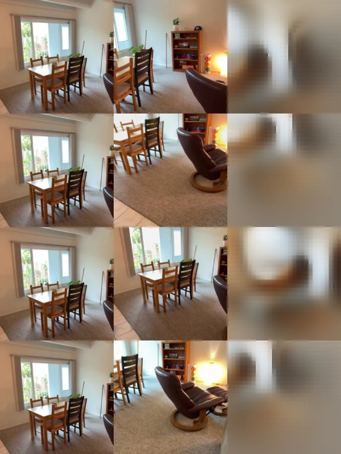
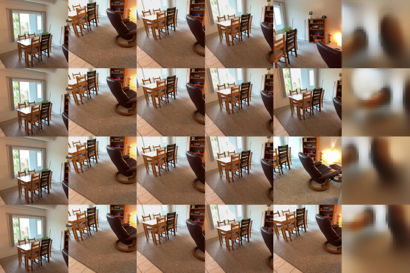
The same two-source-view evaluation setting is shown with the correct target rays, rays shuffled between targets, and zero target rays.
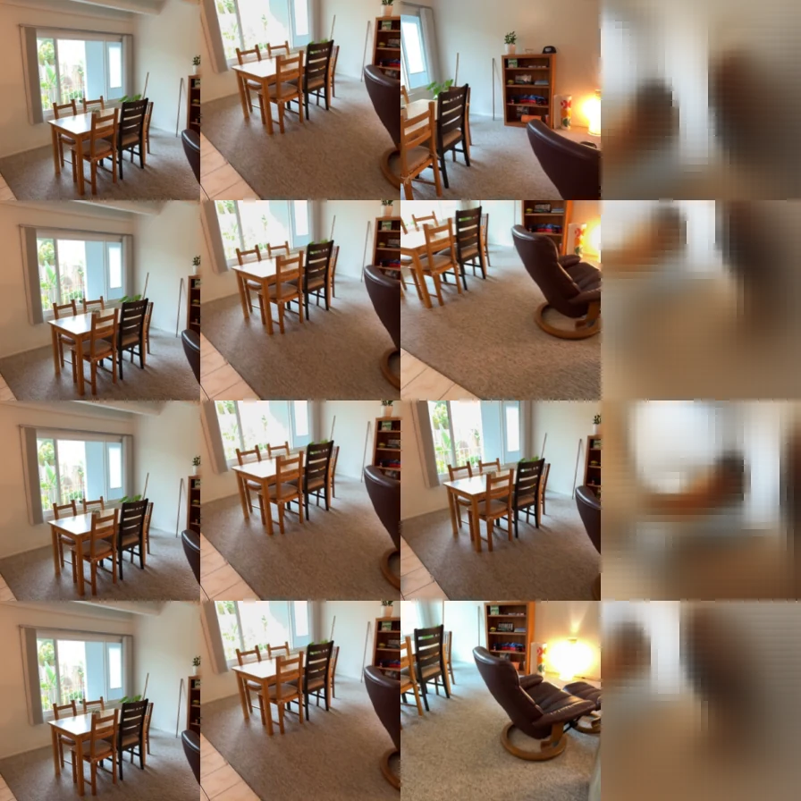
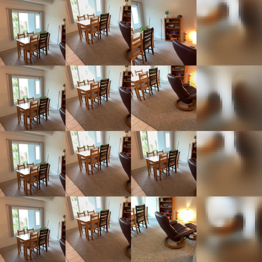
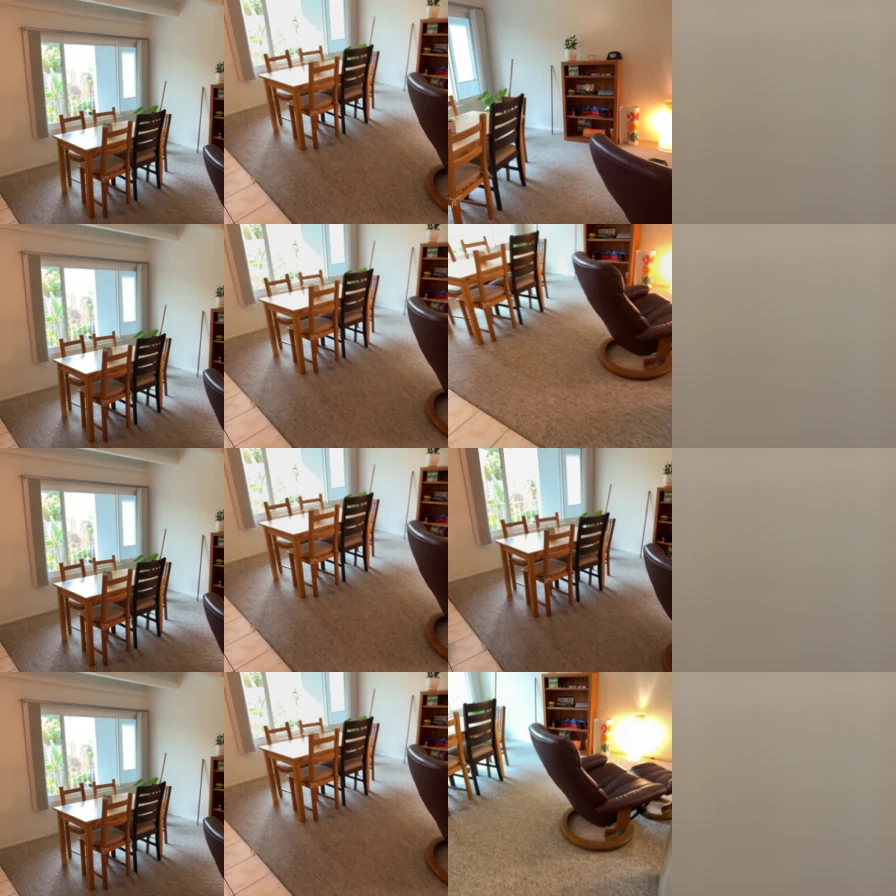
Additional evaluation visualizations: 1 view, correct · 4 views, correct.
Predict the structure behind the views.
Mini-VGGT takes RGB images and predicts cameras and depth. Alternating frame and global attention lets each view reason locally and exchange information across the scene.
RGB → DINOv2 → frame / global attention → cameras + depth
A frozen DINOv2 encoder produces patch features. A camera head predicts pose and field of view; a depth head predicts per-pixel depth and confidence.
Fixed-clip overfit
CompletedThese metrics are measured on the fixed training clip used for overfitting, not on held-out scenes. Training used 40 epochs, 25 steps per epoch, batch size 1 and eight views.


Generalization to unseen scenes
Evaluation complete
Held-out results
| Metric | Validation | Test |
|---|---|---|
| Depth AbsRel ↓ | 0.1421 | 0.1494 |
| Depth δ1 ↑ | 0.8332 | 0.8259 |
| Rotation AUC @ 5° ↑ | 0.1842 | 0.2153 |
| Rotation AUC @ 15° ↑ | 0.5060 | 0.5477 |
| Rotation AUC @ 30° ↑ | 0.6952 | 0.7334 |
| Translation AUC @ 5° ↑ | 0.0176 | 0.0105 |
| Translation AUC @ 15° ↑ | 0.0863 | 0.0809 |
| Translation AUC @ 30° ↑ | 0.1993 | 0.2009 |
| Joint pose AUC @ 5° ↑ | 0.0033 | 0.0026 |
| Joint pose AUC @ 15° ↑ | 0.0610 | 0.0591 |
| Joint pose AUC @ 30° ↑ | 0.1756 | 0.1803 |
Full validation and test splits, 28 scenes each, using the same best-validation checkpoint.
Depth accuracy is similar across validation and test (AbsRel 0.1421 vs. 0.1494). Translation-direction AUC is substantially lower than rotation AUC, indicating that relative translation remains more difficult on these held-out scenes.
Validation geometry results
Compare ground-truth and predicted cameras and depth on the held-out scenes.
Held-out scene comparisons
Scene 09c1414f1b


Scene 21d970d8de


Scene 280b83fcf3


Scene 2b1dc6d6a5


Required evaluation: eight views from the first 32 prepared frames, image size 224, seed 825. Run both full splits without a batch limit.