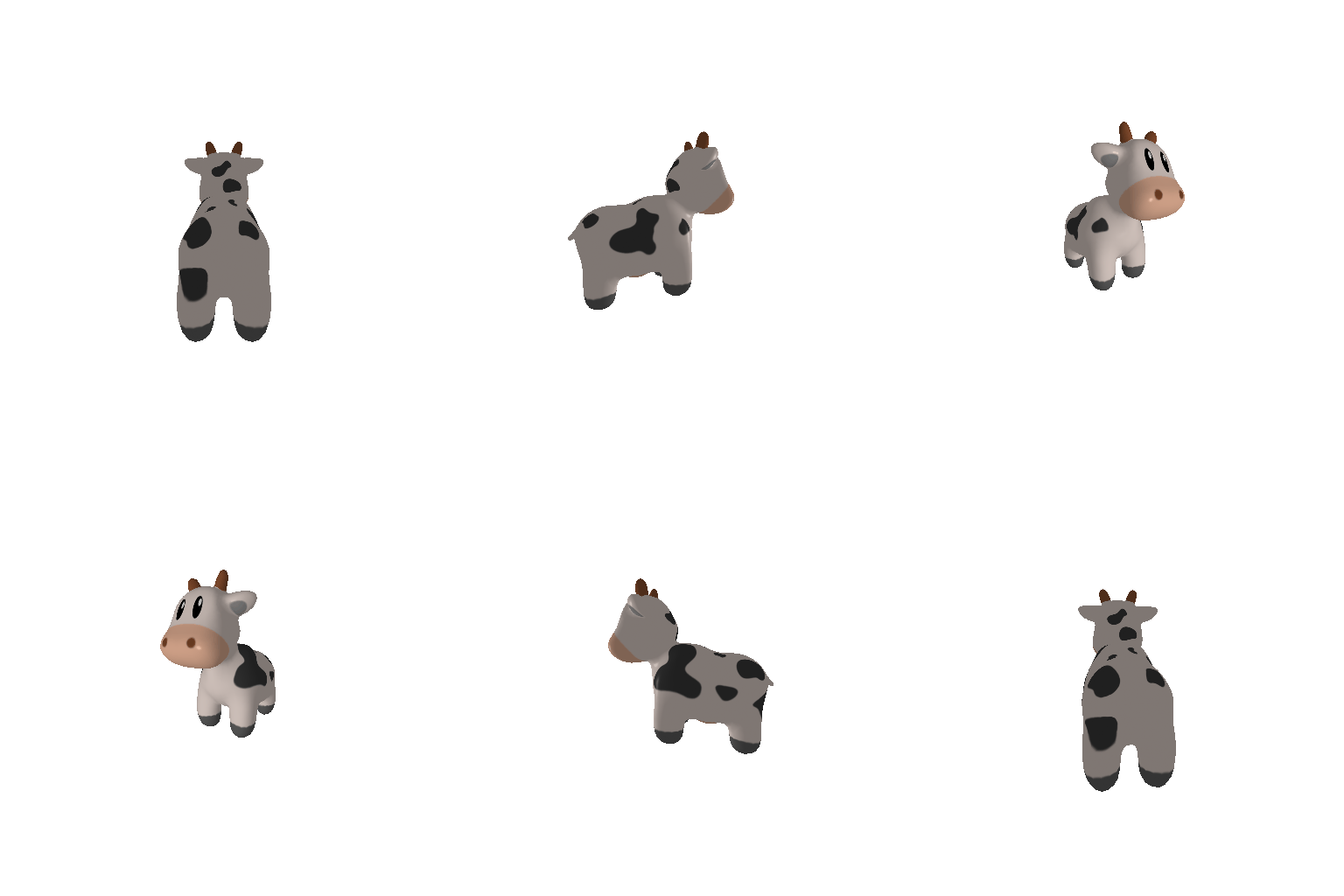
1.1 360-degree Render
I rotate the camera around the cow by varying the azimuth angle while keeping the distance and elevation fixed. The frames are combined into a looping GIF to create a turntable visualization.
CMU 16-825 • Learning for 3D Vision
Camera control, triangle meshes, texture interpolation, RGB-D point clouds, parametric surfaces, implicit surfaces, and creative 3D rendering.
Overview
This assignment explores the basic PyTorch3D rendering pipeline and several common 3D representations. I use cameras, lights, triangle meshes, per-vertex textures, point clouds, parametric surfaces, and implicit functions to generate the visual results shown below.
1. Practicing with Cameras
I rotate the camera around the cow by varying the azimuth angle while keeping the distance and elevation fixed. The frames are combined into a looping GIF to create a turntable visualization.
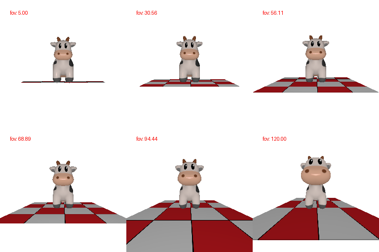
The field of view and camera distance are varied together so the subject remains approximately the same size while the perspective distortion changes.
2. Practicing with Meshes

The tetrahedron is constructed manually from 4 vertices and 4 triangular faces.

The cube uses 8 vertices and 12 triangular faces. Each square side is represented by two triangles.
3. Re-texturing a Mesh
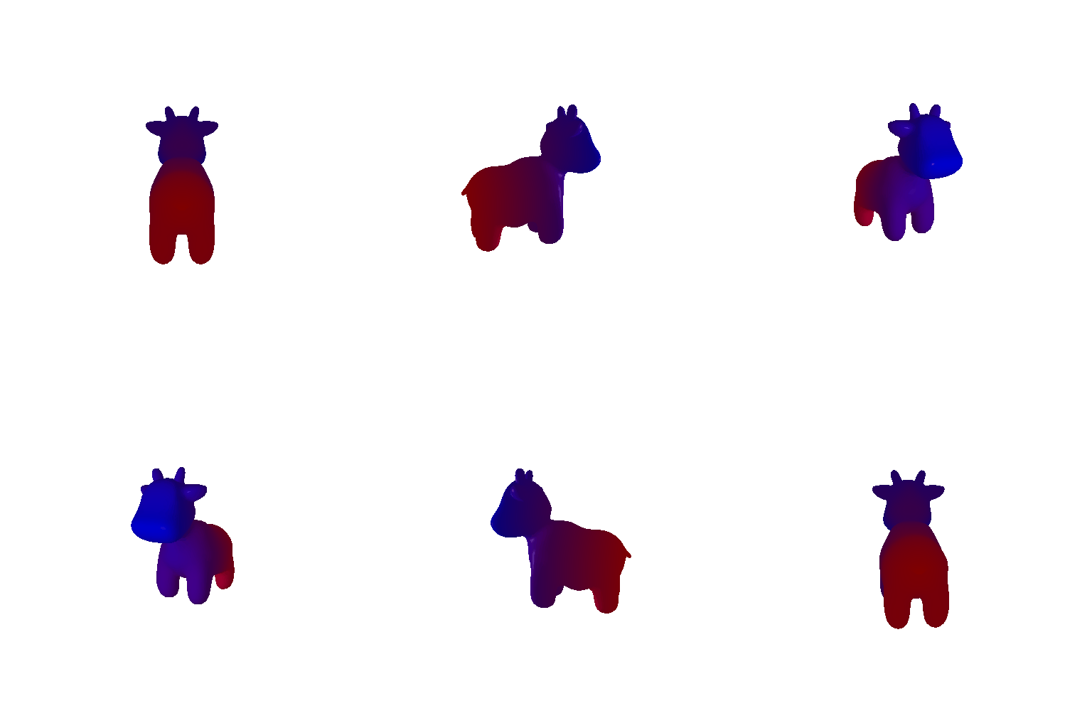
I use the z-coordinate of each cow vertex to interpolate between two RGB colors. The front of the cow is blue and the back is red.
4. Camera Transformations
Each target view is obtained by applying a relative transform to the original camera extrinsics:


5.1 RGB-D Point Clouds
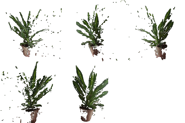
The RGB-D images are unprojected into world-space point clouds using the provided camera intrinsics, extrinsics, depth map, and RGB image. I render the first view, the second view, and their union.
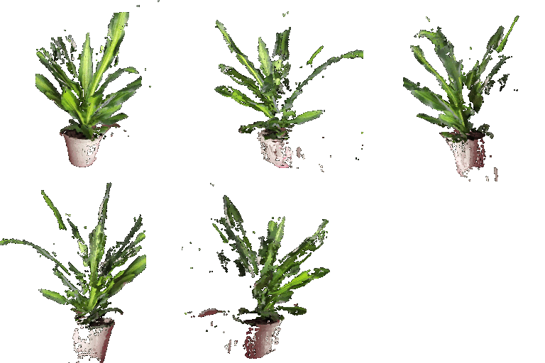
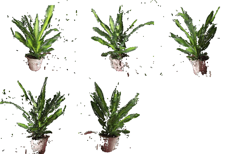
5.2 Parametric Functions
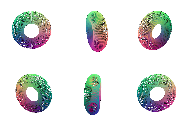
A torus is sampled from its parametric function on a regular 2D grid and rendered as a point cloud. The 360° view makes the central hole visible.
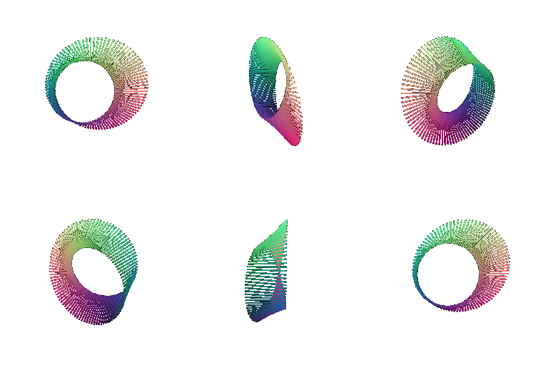
As an additional parametric object, I sample a Möbius strip and render the resulting point cloud from continuously changing viewpoints.
5.3 Implicit Surfaces
For implicit surfaces, I evaluate a scalar function on a 3D voxel grid and use Marching Cubes to extract the zero level set as a triangle mesh.

The torus is represented by an implicit function and converted to a mesh with Marching Cubes.

The Gyroid demonstrates how an implicit representation can generate complex surfaces without manually defining vertices and faces.
Explicit connectivity produces continuous surfaces and generally cleaner shading. Meshes are especially convenient for surface rendering, but the topology and face information add complexity and memory overhead.
Point clouds are simple to construct and manipulate, but rendering quality depends strongly on sampling density and point radius. Sparse point clouds can contain visible holes and do not explicitly encode surface connectivity.
Extra Credit 6

I create multiple moving scalar-field centers and extract a new implicit surface at every frame. As the centers move, the components smoothly merge and separate, producing an animated metaball-like structure.
Extra Credit 7
Instead of using the mesh vertices directly, I sample the cow surface using area-weighted face sampling and uniform barycentric coordinates. This avoids over-representing regions composed of many small triangles.


Implementation