Return to the lecture notes index
Lecture 2 (August 27, 2010)
What is a Database?
Okay. I don't want to beat this one to death. You may not be able to
offer a perfect formal definition of a database, but I bet you
know one when you see one. In casual terms, a database is a bunch of
data and everything else needed to add more, take some away, and otherwise
dig through it to get to the bits we need. So, let's move on and, for the
record, somewhat carefully define and distinguish among some similar,
database-related terms.
The most general definition of database is probably "A collection of
data." But, a definition this unbounded doesn't really give us a hint about
the important properties or uses of a database. We can probably do a little
better. And, "Database Management System (DBMS)" and "Database System" are
confusingly similar. Let's take a minute and define these terms in a meaningful,
descriptive (I hope!) way:
database, def.: "a collection of data structured and organized
to be convenient and efficient to access."
database management system (DBMS), def.: "The combination of a
database, itself, and the software that access, maintains, and manages it."
database system, def.: "An all-encompassing term that includes
the DBMS, the underlying database, the hardware, the supporting software,
such as the operating system, and other aspects of a database's deployed
environment."
Okay. Now that we've covered the formal definitions, I'm going to go back
to being casual. I'll often use the term "database", whether I actually
mean the underlying database, the DBMS, or the entire system." But, no worries,
the context will give me away.
Databases vs Filesystems
A file is a named chunk of (usually persistent) data. A
file system is the software layer responsible for organizing, storing,
and accessing files. It is usually responsible for managing the underlying
storage, providing primitives, such as read() and write(), for using a file
one located, and for providing a way to locate a file given its name.
The critical difference between a file system and a database is that a file
system is ignorant of the structure or relationship among the data within
the files. Instead, the use of the data within the files is the responsibility
of a client program. By contrast, a database is responsible for maintaining
the structure of the data and the relationships therein. Furtheremore, whereas
file systems typical locate files by their prescribed names, databases can
locate records by their properties and relationships.
Databases prevent the reinventing of the wheel by providing a powerful,
resilient, and reusable and multi-use toolkit for using data and help
to bridge the gap between data and information.
data, def.: "measurements or values, without the perspective
or context to give them meaning."
information, def.: "data viewed from a context or point of
view in which it can be interpreted, understood, or found to have meaning."
When we access data via a file system, such as by browsing files in
Windows Explorer or the directory listing of a UNIX system, we are seeing
the files organized by name. The file system allows us to read and write
the content of these files, but in a very raw way that is ignorant of
its structure. The application programs that make use of the file system
created these files, and only they know and are able to leverage their
organization.
Not unlike the way file systems allow us to access files by their names,
databases allow us to access records by their primary keys. But,
more importantly, because databases understand much about the data's
structure, we can also ask them to deliver us collections of datum that
matches particular criteria and/or has particular relationships with other
datum.
The Database Design Process
I'd like to speak for a few minutes about the process of high-level database
design. What I mean by this is that I'd like to talk about how we can use
a methodological, process-oriented approach to developing a solution
to a problem using database technology. Interestingly enough, if you've
ever done or studied any true aoftware engineering, this process is bound
to sound very familiar. Real people, real problems, a real process, and
real documentation are a big part of many design processes.
- Requirements Analysis: The first step is what we call
Requirements analysis. In other words, we need to elicit
from the client what we are required to do. At this stage, we aren't
trying to determine how to solve the problem, what technologies to use,
or anything like that. We're trying to figure out why we are involved:
What problem needs to be solved? This is often times a personal
process. A technical professional, though maybe not a database person,
talks with the client, and assertains what data they have, how
it is organized, how it is managed and used now, and what they'd
like to do with it. An attempt is also made to look into the
crystal ball and to ask how the available data, needs, and systems
might change in the future.
The result of this process is a design document called a User
Requirements Document (URD). This document captures the user's
expectations of the final product. These expectations are usually
structured into two categories, functional requirements
and non-functional requirements. Functional requirements
describe what the software "shall do". Non-functional requirements
describe qualities of the solution, e.g. speed and storage efficiency,
throughput, reliability characteristics, etc. These requirements
are often expressed as, "shall be" (as contrasted with "shall do").
Sometimes, in addition to (or instead of) the URD, we produce a
use case document. A use case document expresses the
functional requirements through a list of scenarios, or interactions
with the software. Basically, it describes how the system reacts
to outside requests. Sometimes, the analyst distills the URD from the
use cases.
The long and the short of it is that the functional requirements will
eventually externaly visible features of the system, whereas the
non-function requirements will drive its internal design.
In the everyday case of databases, the functional requirements will
often drive what data is stored, how it is organized, and the features
of the appliction. By contrast, the non-functional requirements will
drive the tuning of the database, and the configuration of the
underlying hardware, e.g. storage, backup system, etc.
It goes without saying that the requirements analysis , because it is
so tied to the business problem, is usually done by a domain
specialist, e.g. someone who knows the client's industry, rather
than soneone who specializes in the internals of databases.
- High Level Design: Once the user's requirements are
understood, we know the problem that we need to solve. We now need
to move in the direction of actually solving it. At the high-level
design phase, we document the details of what information is
available and how it relates. This produces another type of design
document that is specific to the data model that will be used in
the eventual solution. So, a decision about that model, e.g.
object-oriented, relational, semi-structured, object-relational, etc.,
also needs to be made as part of this process, at least if it was not
explicitly required by the user as part of the non-functional
requirements.
This class focuses on relational databases. So, we'll be using the
Entity-Relationship (ER) Model to represent our data. We'll be
documenting this information using Entity-Relationship Diagrams
(ERDs). The resulting document representation of the database's
organization is known as a High-level schema or Abstract
schema.
- Logical Design: In the logical design phase, the
high-level design using standardized notation is translated into
a representation that exactly matches, and is understandable by,
the database system that is actually used. At this phase, a
first attempt is made to eliminate redundancies, remove conflicts,
and ensure that everything is in place. This representation is known
as the database's logical schema.
- Schema Refinement: In this phase, also known as
Normalization, in what is a somewhat algorithmic process,
database theory is used to translate the original form of the
high-level schema itno a normal form, that is known
to be free of unnecessary redundancies, conflicts, etc.
- Physical design: Once we know how the data will be organized
and how we'll be using it, we can turn out attention to the
machinery. In the physical design phase, we worry about
performance-altering decisions, for example how we'll lay out
indexes, organize clustering, tuning the database, etc. Sometimes
the schema may be altered to improve performance, e.g. minimize hot
spots.
- Security design: Okay. We list this last, not because it is
unimportant, but becuase securty is its own discipline. Certainly
databases can have some sense of ownership, read/write/modify
bits, etc. But, this isn't security in the real world. Most of
database security is really the providence of enterprise-level
security (Who is using the database? How do we know? Are they allowed?
How do we know?) and application-level security (What can a user of
class-X do?)
The problem of what an individual user might, or might not, be able to
is really more of a question of business logic than access bits.
Information security is very complicated. For example, imagine that
we want managers to be able to query a database to learn how persons
in a particular job class are compensated. But, we do not want them
to be able to find averages for protected classes, e.g. women (or in
some professions men), ethnic minorities, those with disabilities, etc.
This is harder than it seems. Let's say that we don't let managers
find salary averages for women. Easy enough. But, what if they
find out how many men there are, how many women there are, the
average compensation, and the average compensation for men. And then
they, well, apply math. "Ta da!"
...information security, at least in a meaningful way, is its own
course -- and then some!
Types of Databases
Databases can be structured in many different ways. These days, most
databses are relational database. Relational databases structure the
data into tables, where each row of a table represents a record and each
column represents an attribute of that record. Record types aren't mixed
within a table, or are they nested. The simplicity of the data combined with
the rigid structure allows for very efficient, very powerful querying. This
semster is mostly about relational databases.
Object-oriented databases, allow much more sophisticated entities. Rather than
a very structure set of fairly unexpressive properties, they can contain
very sophisticates types and subtypes and can include methods in addition to
pure data. Think of a database of Java objects.
Object-relational databases allow rich objects to be used as data,
while maintaining enough structure to support relational queries (Let's
not talk about the overhead).
Semi-structured databases aren't really databases, but we'll
pretend. This space, these days, is basically owned by XML documents.
They contain collections of objects, but each of which may have a different
structure. The reality is that, for the most part, XML documents are
interesting from the perspective of information retrieval, not large-scale
databases, for which they'd be inefficient.
...and there are many, many other types of databases.
Database Languages
Databases designers and application programmers need a way to describe
the structure of the data and to interact with the database. Formally,
a language that describes the structure of the data is known as a
Data Description Language (DDL), and a language that describes
the manipulation of the database is known as a Data Manipulation
Language (DML). In reality, these languages are often one-and-the-same,
or very closely coupled, as is the case with SQL.
Incidentally, high-level designs may be documented using specific notations
that have specific rules. These are often called design languages
or modeling languages. UML, which we briefly mentioned earlier, is
one such language.
The Entity-Relation Model
As I've mentioned before, the bulk of this course focuses on relational
databases. The most common high-level model for relational databases is
the Entity-Relation (ER) model. It won't come, I hope, as a surprise
to any of you to learn that the ER model represents a database's logical
design in terms of entities and their relationships.
What is an entity? What is a relationship? Don't make this hard. Don't even
think of making this hard. Don't spout any theory. Don't babble anything
formal. Remember, we're talking about the high-level, abstract design.
It is about the user, and the user's expression of the problem.
"Entities" are "things" (or "objects", read casually) in the real world,
in the context of the user's problem. If you are considering a student
information system, the entities might be students, courses, and transcripts.
If you are thining about a payroll system, the entitites might be employees,
timecards, and pay stubs.
And, "relationships" are exactly what you think they are. They describe
how the entites come together. For example, a student might be related
to a class by virtual of being "enrolled" (a relationship). An employee
might be relayed to a paystub by having "earned" the money, or perhaps
by "compensated" the money for vacation, an injury, etc.
Both relationships and entities can have attributes. An employee
might have a name, SSN, and birthdate. The "enrolled" relationship
between a student and a class might have an attribute of "credit/audit"
and/or "pass-fail/letter".
The domain of an attribute is a categorization of the values that it
can hold, e.g. "20 character string", "number", etc. This is a categorization
at the level of the data -- not one that is imposed by the circumstances.
Limits on the values that data may hold that are dependent upon the
circumstances must be enforced by the business logic, rather than described
by the data mode, so they aren't properly part of the ER model. It is also
worth noting that databases do not generally have very rich type systems, so
the domain of the value, as described in the ER data model, is likely to be
a pretty broad category.
If we think about an instance of an entity, an entity set is
an instance of an (unordered) collection of instances of the same entity,
in other words, it is one or more of the same entity. An entity set might
result from some databse operation, e.g. query. Similarly, an instance of a
relationship set is a set of relations.
We're going to use the term key a little different that you probably
have in the past. For our purposes a key is some set of attributes that
can be used to uniquely identify an instance of an entity. If the "key"
attributes match, the other attributes are guaranteed to match. Some books
call this a superkey.
We are often interested in a "minimum key" of sorts, a key that contains only
essential attributes. We call this a candidate key. Imagine that we can
uniquely identify a car by license plate number and state. Clearly these
two pieces of information form a "key" for the car. As a result, the
set containing the license plate, the state, the car color, and the number
of scratches on the right door can also be used to identify a particular
instance of a car, but contains attributes not needed for this purpose.
Both sets of attributes are keys, but only the first is a "candidate key".
It is important to note that an entity of a particular type might have
multiple candidate keys. For example, assuming we are guaranteed to have all of the following information for each student, we might be able to uniquely
identify a particular student by <SSN>, by <University,
Student ID>, or by <State, TaxId>. Each of these tuples
represents a candidate key, because if we eliminate any attribute from any
tuple, the tuple no longer identifies exactly one student.
Although multiple candidate keys might exist, the database designer often
picks exactly one key to serve as a name for the entitity. We call this
key the primary key. And, to reiterate for those in the back --
the primary key need not be a single attribute, it need only be a
candidate key. Although any candidate key will do for definitional
purposes -- there surely may be good reasons to pick one candidate key over
others.
Entity-Relationship Diagrams: Exploring the Model
Let's take a look at how we can draw some figures to describe entites,
relationships, and some of their friends.
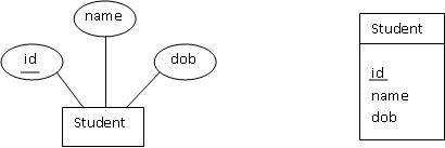
First, let's consider an entity set known as a student that can
consists of an <id, name, date-of-birth(dob)>. The figures below
both depict this type of entity set. The first one uses a traditional
database notation. The second one substitues a UML-like notation for
the "bubbles" traditionally used for atrributes. I'm going to do this
in class, because it is much faster and more dense to draw on the board
this way. And, since UML does it, I have an excuse. In each case, the set of
attributes forming the primary key is underlined.
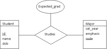
The figure below shows the use of a "diamond" to represent a relationship set,
as contrasted with the squares we used to represent entities. Note, though,
that I am going to the traditional ERD bubbles to represent attributes for
relationships. I don't want to go off the deep end with UML notation, which
can be quite rich, as it was designed to describe objects in software systems,
e.g. Java and C++. So, here you have it, a student "studies" in a major:
Please notice the "arrow" in the figure below, which is otherwise the
same as the one above. This arrow indicates that each instance of a
student has at most one major (this is obviously not the case at
Carneige Mellon).
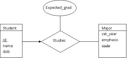
Student question: What about case X? Or case Y? How do I draw the arrows?
Answer:: Maybe you don't. This arrow notation is not nearly as expressive
as we'd like. It works nicely for binary relationship -- but higher order
relationships are a mess.
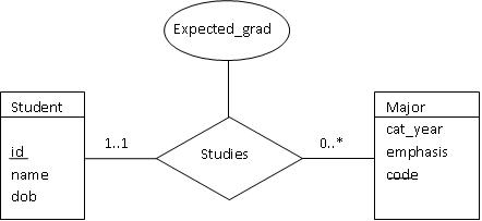
More complex constraints on relationships are noted on the edges, as shown
below. This particular figure shows a world in which a student has exactly
one major, but a major can have 0 or more students enrolled.
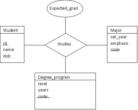
The figure below indicates a ternary relationship. The "studies"
relationship now involves a student, a major, and a program. Note that
the relationship really is ternary -- a student studies in a particular
major in a particular degree program. For example, many students might
study in computer science, many students might be in the B.S. or Ph.D. program,
but the studies relationship paints the complete picture by binding all three.
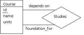
Sometimes the same entity can play different roles in the same relationship.
We call these situations non-binary relationships. Consider the ER
diagram below, which shows a course serving as a prerequisite for another
course. The course entity is drawn only once, but there are two different
edges connecting it to the prerequisite realtionship. Each of these edges is
labeled with the role that it represents. We call this label the
role indicator.
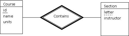
Consider a (recitation) section of a course, described by its section_letter and
instructor. Although a section is an entity, it cannot stand by itself. For
it to be meaningful, it must be tied to a course. If I tell you tell me that
you are "in section A with Kesden", you cannot identify the section -- you need
to know if it is "section A" of 15-415, 15-440, or 15-123, etc.
We refer to a set of these dependent entities as a weak entity set and
the set of entites that it is dependent upon as the owner entity set.
An entity from the weak entity set can only be identified when combined with
the primary key of its identifying owner from the owner identity set.
For this to work, each entity from the weak entity set must have exactly one
owner in the owner entity set. (Entities in the owner set can map to multiple
weak entities...consider sections of a course). This is sometimes expressed
as follows:
- There is a one-to-many relationship between owner entities and dependent
entities. In other words, in our example, a course can have more than
on section, but not the other way around.
- There must be total participation of the entities of the dependent
set in the owner set. In other words, given our example, no section
can be without a course.
The diagram below shows the "darkened diamond" we used to represent the
relationship of the dependent and owner entity sets. Also notice that we use
a dasked line to indicated the partial key within the weak entity set.
It is possible to have different types or specializations of the same base
entity. Think inheritence in Java or C++: We can subclass here, just the same.
The figure below shows how we can use a triangle to document the existence of
two different types of student entities: undergraduates and graduates.
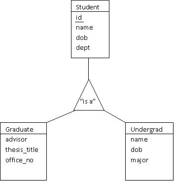
It is important to note that this notation is far less expressive than we'd
like. And, it si far less expressive than other, more sophisticated
notations, such as UML. For example, is Student an abstract class? In other
words, can one be a student, without being a graduate or undergraduate student?
Can one be both a graduate student and undergraduate student at the same time
(consider ECE's IMB program or the Tepper-SCS 3-2 MBA program)?
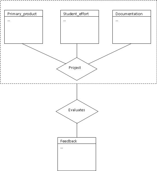
In the last example for today, it is possible to Aggregate entities
tied together by relationships in order that the aggregation can be treated
as an entity and take part in relationships with other entities. Consider
the situation of a team project which consists of the primary_product, the
students who participate in the project, the documentation they produce.
The evaluation of this project depends on the quality of the product, the
quality of the documentation, and the quality of each student's effort to
produce feedback.
We could represent this by showing each of the primary_product,
the students' effort, and the documentation in a project. And,
we could show the evaluation exactly the same way. But, this is needlessly
complex and lacks clarity. Instead, we want to aggregate the constituent
parts of the project show them in a relationship with the feedback, as
shown below. Notice the use of the dashed box to represent the aggregation.
Semtimes folk are confused about when to use a ternary (or higher-degree)
relationship and when to use aggregation. Don't think to hard on this one.
Use aggregation if you want an aggregate to, as a whole, participate in a
relationship. Use a higher-order relationship, when multiple individual
parts are participating. If you are unsure, draw it both ways: The simplier
figure will likely be correct.