|
Carnegie
Mellon University Mechanical Engineering |
Problem 5 : Double Edge Crack in Finite-Width Sheet
|
Carnegie
Mellon University Mechanical Engineering |
Problem
Description
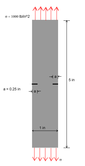
# Material : The plate is made of steel with Modulus of
elasticity E = 30,000 ksi, and Poisson's ratio = 0.3
# Unit : U.S. Customary Units ONLY. It is important to convert all forces to
"lb" and all dimensions to "in".
# Boundary Conditions : The plate has two cracked edge, one is on the right
side and the other is on the left side of the plate
# Loading : Uniform tensile Load with magnitude 1000 lb/in^2 acting on the
top and bottom of the plate.
# Objectives :
1. To determine stresses in y direction along the line of cracked edge and how much the cracks open up after load is applied to it.# Figure :
2. To model the plate using diffferent number of mesh elements in the area where stress and displacement are of concern.
1.
Specify Geometry
Click on the following in the drop down menu on your right.
PREPROCESSOR -> -Modeling - Create
CREATE -> -Keypoints
KEYPOINTS
-> In Active CS...
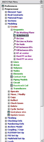
The input box "CREATE KEYPOINTS IN ACTIVE CS" should now appear
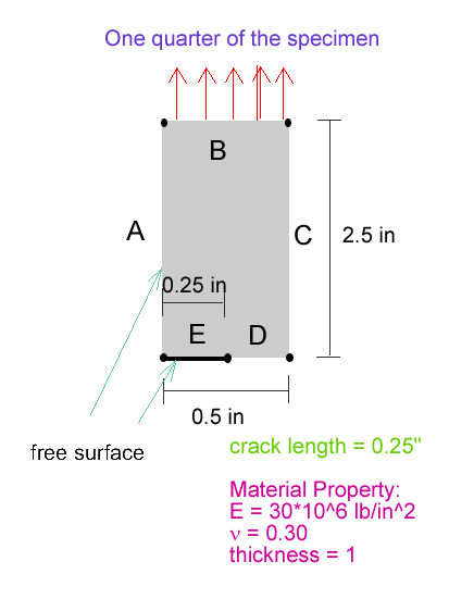
on the screen. According to the problem description, we have to create a
plate with dimensions of 0.5 inch wide and 2.5 inches high. Enter the corresponding
x and y coordinates in the box as shown in the figure below. This will create
a rectangle of size 2.5 inches x 0.5 inch.
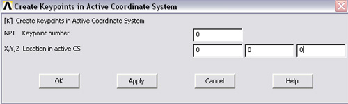
Point 0 -> (0,0,0)
Point
1 -> (0.25, 0, 0)
Point
2 -> (0.5, 0, 0)
Point
3 -> (0.5, 2.5, 0)
Point 4 -> (0, 2.5, 0)
Note:
You need not start your index at 0. It can be any number as long as you
know the numbering scheme of those keypoints
After finish entering all the values, click OK. Then we need to create
line A, B, C, D and E. After we finished creating those lines, then we need
to create an area. Steps are as follows.
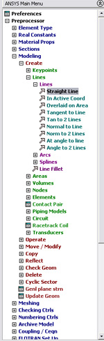
Then
click on keypoint 0, 1 and APPLY. Then repeat the process for 1 and 2. And
so on.
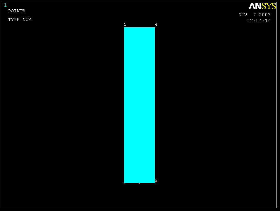
You should be able to see 5 lines around the rectangle.
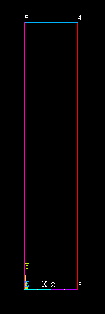
The next step is to create an area inside those 5 lines.
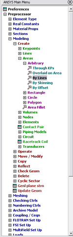
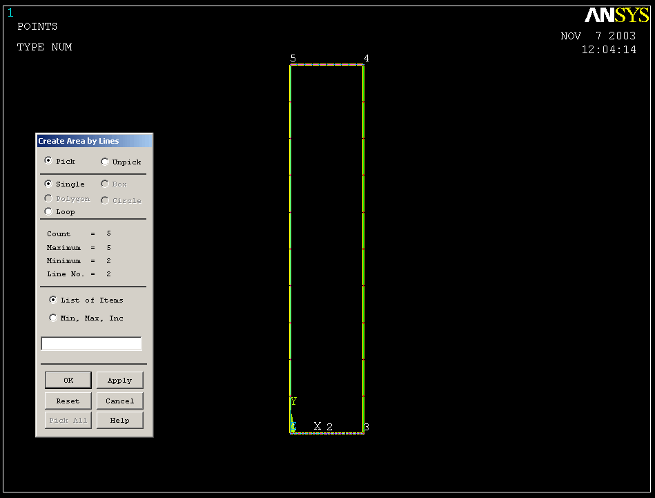
Click OK. Now
the blue rectangular plate should appear on your ANSYS GRAPHICS window.