Structural #4: Analysis
of a 3-D truss structure
Introduction:
In this
example you will learn to use the 3-D Truss element in ANSYS.
Physical Problem:
Analysis of the 3D truss structure shown in the figure below.
Problem
Description:
 |
The tower is made
up of trusses. You may recall that a truss is a structural element
that experiences loading only in the axial direction.
|
|
Units: Use S.I.
units ONLY |
|
Geometry:
the cross sections of each of the truss members is
1.56e-3 sq meter. |
|
Material: Assume
the structure is made of aluminum with modulus of elasticity E=75
GPa.
|
|
Boundary
conditions: The structure is constrained in the X, Y and Z directions
at the bottom three corners. |
|
Loading: The tower
is loaded at the top tip. The load is in the YZ plane and makes an
angle of 75 with the negative Y axis direction. The load value is 2500
N. |
|
Objective:
 |
To determine
deflection at each joint. |
|
To determine
stress in each member. |
|
To determine
reaction forces at the base. |
|
Give three
examples where similar 3D trusses are used in practice. Model one of
them (with reasonable assumptions of dimensions, material properties
and loading) using ANSYS. You don't have to solve it. You can do so
to check whether your assumptions were reasonable!! |
|
|
You are required to
hand in print outs for the above. |
|
Figure:
 |
|
IMPORTANT:
Convert all
dimensions and forces into SI units. |
STARTING ANSYS
|
Click on ANSYS 6.1
in the programs menu. |
|
Select Interactive.
|
|
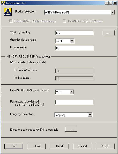
The following menu
that comes up. Enter the working directory. All your files will be
stored in this directory. Also enter 64 for Total Workspace and 32 for
Database. Give your file an appropriate job name. |
|
Click on Run.
|
MODELING THE
STRUCTURE
|
Go to ANSYS Utility
Menu. Click on
Workplane>Change
Active CS to..>Global Cartesian.
|
|
Go to the ANSYS
Main Menu. |
|
Click
Preprocessor>Modeling>Create>Keypoints>In
active CS
|
|
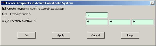
The following
window comes up |
|
Fill in the
keypoint number (1,2,3...)
and the coordinates. Make sure you get the correct coordinates from
the figure. Create all the 10 keypoints.
Make sure the numbering of your keypoints
matches the numbering of the joints in the figure. |
|
If you cannot see
the grid then go to
Utility Menu>Display Working Plane
|
|
If you cannot see
the complete figure then go to
Utility Menu>PlotCntrls>Pan Zoom Rotate
and zoom out to see the entire figure. |
|
Now create lines
connecting the keypoints
|
Click on
Preprocessor>Modeling>Create>Lines>Lines>In Active
Coord.
|
|
Pick the
endpoints of each element to create the lines. Rotate the figure
for more accessible views. |
|
|
You can use the
Utility Menu>PlotCtrls>Pan Zoom Rotate
window to rotate the model and see its 3D nature. |
|
MATERIAL PROPERTIES
|
Go to the ANSYS
Main Menu |
|
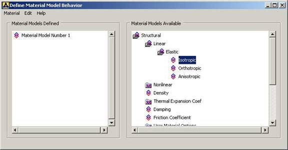
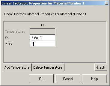
Click
Preprocessor>Material Props>Material Models.
In the window that comes up which is shown below, for Material Model
1, choose
Structural>Linear>Elastic>Isotropic.
|
|
Double click
Isotropic for Material Model 1. |
|
Fill in 7.5e10 for
the Young's modulus and 0.3 for minor Poisson's Ratio. Click OK
|
|
Now the material 1
has the properties defined in the above table. We will use this
material for the elements of the structure. |
ELEMENT PROPERTIES:
|
SELECTING ELEMENT
TYPE:
|
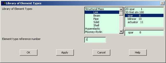
Click
Preprocessor>Element Type>Add/Edit/Delete...
In the 'Element Types' window that opens click on Add... The
following window opens. |
|
|
Type 1 in the
Element type reference number. |
|
Click on Structural
Link and select 3D spar. Click OK. Close the 'Element types' window.
|
|
So now we have
selected Element type 1 to be a structural Link- 3D spar (cable)
element. The trusses will be modeled as elements of type 1, i.e.
structural link element. This finishes the selection of element type.
|
|
Now we need to
define the cross sectional area for this element. |
|
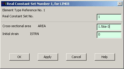
Go to
Preprocessor>Real Constants.
|
|
In the "Real
Constants" dialog box that comes up click on Add |
|
In the "Element
Type for Real Constants" that comes up click OK. The following window
comes up. |
|
Type 1.56e-3 for
cross sectional area and click on OK. |
|
We have now defined
the cross sectional area of the link element. |
MESHING:
|
DIVIDING THE TOWER
INTO ELEMENTS: |
|
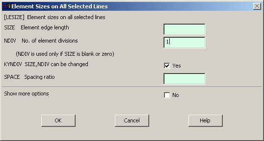
Go to
Preprocessor>Meshing>Size Controls>Manual Size>Lines>All Lines.
In the menu that comes up type 1 in the field for 'Number of element
divisions'. |
|
Click on OK.
|
|
Now go to
Preprocessor>Meshing>Mesh>Lines.
|
|
Select all the
lines and click on OK in the "Mesh Lines" dialog box.
|
|
Now each line is a
truss element (Element 1). |
BOUNDARY CONDITIONS AND
CONSTRAINTS
|
APPLYING BOUNDARY
CONDITIONS
|
The tower is
constrained in the X, Y and Z directions at the four bottom corners.
|
|
Go to Main Menu
|
|
Click on
Preprocessor>Loads>Define Loads>Apply>Structural>Displacement>On
Keypoints
|
|
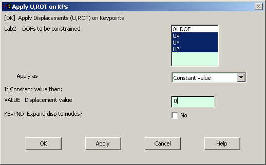
Select the
keypoint on which you want to apply
displacement constraints. The following window comes up.
|
|
|
Select UX, UY,
UZ and click OK. |
|
APPLYING FORCES
|
First find the
components of the force along the Y and Z directions |
|
Go to Main Menu
|
|
Click on
Preprocessor>Loads>Define Loads>Apply>Structural>Forces/Moment>On
Nodes.
|
|
Select the top
node. |
|
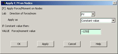
Click on OK in
the 'Apply F/M on Nodes' window. The following window will appear.
|
|
Enter the value
of the Z-component of the force. |
|
Repeat the
procedure to apply the Y-component of force. |
|
|
Now the Modeling of
the problem is done |
SOLUTION
|
Go to ANSYS
Main Menu>Solution>Analysis Type>New Analysis.
|
|
Select static and
click on OK. |
|
Go to
Solution>Solve>Current LS.
|
|
Wait for ANSYS to
solve the problem. |
|
Click on OK and
close the 'Information' window |
POST-PROCESSING
|
Listing the results
|
|
Go to ANSYS Main
Menu |
|
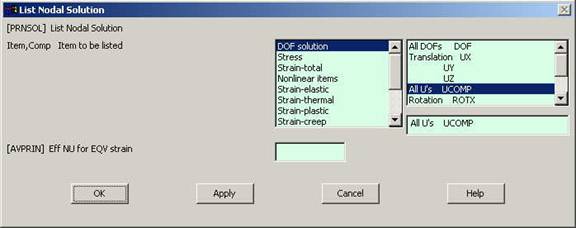
Click on
General Postprocessing>List Results>Nodal
Solution.
The following window will come up: |
|
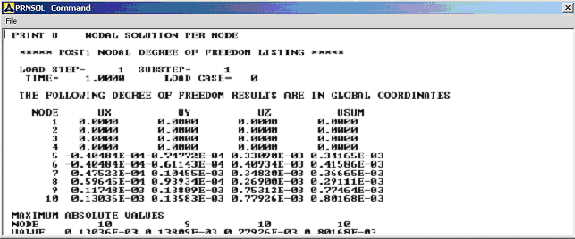
Select DOF solution
and All U's. Click on OK. The nodal displacements will be listed as
follows. |
|
Similarly you can
list the stresses for each element by clicking
General Postprocessing>List
Results>Element Solution.
Now select LineElem Results. |
MODIFICATIONS:
|
You can also plot
the displacements and stress. |
|
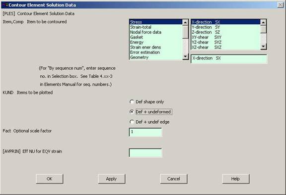
Go to
General Postprocessing>Plot
Results>Contour Plot>Element Solution.
The following window will come up. |
|
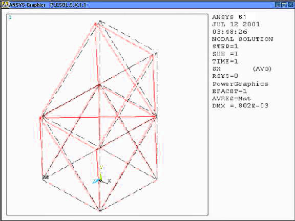
Select a stress to
be plotted and click OK. The output will be like this.
|
|