Heart Model with Valves
|
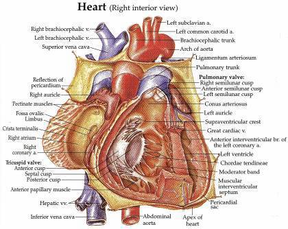
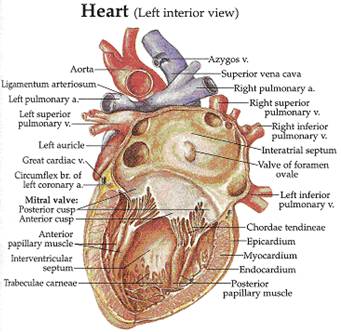
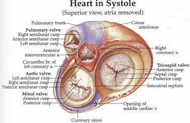
The construction of the human heart model is important for the development of cardiovascular surgical procedures based on simulations of patient-specific models using finite element method. We are trying to construct a tetrahedral heart model with some necessary components, such as aorta, veins, four chambers (left, right atriums and ventricles), heart valves, muscles, etc. The extended Dual Contouring method is used here to build the tetrahedral heart model from volumetric imaging data. 1. Anatomical
charts of the human heart (Figure 1)
Figure 1: Heart Anatomy
Model from [6] 2. Simplified
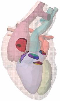
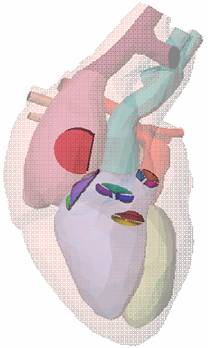
heart model (Figure 2) A
simplified surface heart model (triangular mesh*, Figure 2, download
triangular mesh) is used to construct the tetrahedral mesh. Comparing
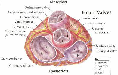
with Figure 1, we can see there are four heart valves (aortic valve,
pulmonary valve, mitral valve and tricuspid valve)
and one valve of foramen ovale (I am not sure if it
is the correct name). (* With permission of
Original model Modified model Figure 2: Simplified Heart
Model
(a) (b) (c) (d)
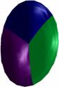
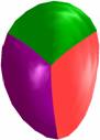
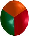
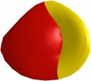
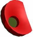
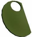
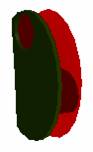
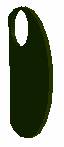
(e) Figure 3: Valves – (a)
aortic valve; (b) tricuspid valve; (c) pulmonary valve; (d) mitral valve; (e) valve of foramen ovale In our finite element model of the human heart, the aortic valve, the tricuspid valve, the pulmonary valve and the mitrial valve should have gaps between its cuspid components, which allow blood flow through the valves. We modified the original valve models (Figure 3 (a ~ d)) to obtain gaps.
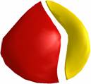
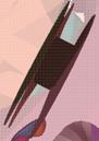
(a) (b) (c) (d)
Original
(e) Modified (e) Figure 4: Valves with gaps
– (a) aortic valve; (b) tricuspid valve; (c) pulmonary valve; (d) mitral valve; (e) valve of foramen ovale. 3. Tetrahedral
meshes of the heart model Considering all the components in the simplified heart
model as only one object. First convert the triangular surface mesh into
volumetric data using signed distance method, then extract triangular surface
meshes (download
triangular mesh) and tetrahedral meshes from it. ·
Heart model with valves, no valve gaps (download
tetrahedral mesh)
(a)
(b)
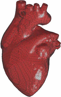
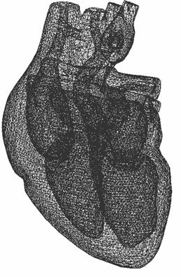
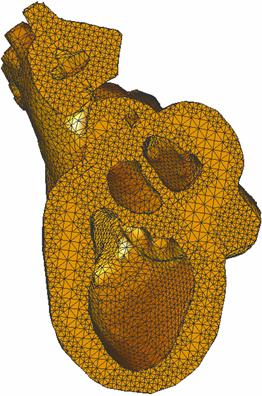
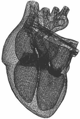
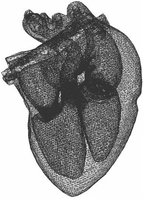
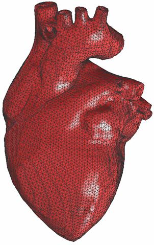
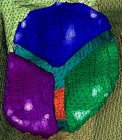
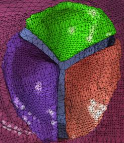
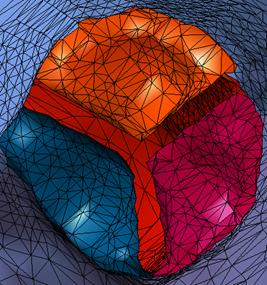
(c) Figure 5:
Tetrahedral meshes of the heart model. (a) – viewed from outside; (b) – inner
structure (wireframe); (c) a cross section of the
tetrahedral mesh of the heart.
In order to keep all the features of the complicated human
heart model (like valves, chambers and blood vessels), and at the same time
minimize the number of elements for efficient finite element calculation, we
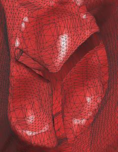
choose adaptive tetrahedral meshes. The valve areas are set the finest level, features based on the Eucliean
error function are identified and preserved. Those areas with thin walls are
refined to keep the correct topology. The following mesh is extracted from a
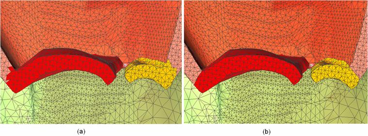
signed distance function dataset with the resolution of 257^3. Bad valve gaps
shown in Figure 7 are introduced because the current resolution is
not high enough.
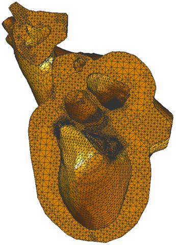
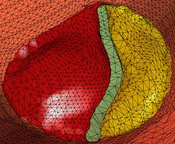
Figure 6: Adaptive
tetrahedral mesh for the heart model with valve gaps. The top row shows the
boundary in wire frame, the meshes in valve areas are finest; The bottom left
is viewed from outside; The bottom right shows a cross section of the
adaptive tetrahedral mesh, the valves have finest mesh, features are
identified using the Eucliean error function, and
preserved by the mesh adaptivity.
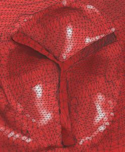
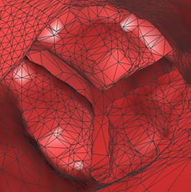
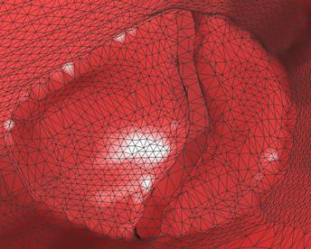
(a) (b)
(c) (d) Figure 7:
Valves with gaps in the adaptive mesh. 4. Boundary
and Material Detection (download
the adaptive tetra mesh with boundary detection)
aortic
valve
tricuspid valve
pulmonary
valve
mitral valve Figure 8:
Boundary detection in the adaptive mesh.
Figure 9:
Material detection in a heart model with the replace mitral
valve. 5. Data Format
(*.raw)
Triangular
Mesh: 36410 159199
// # of vertices (nvert), # of triangle (ntri) -14.649727 6.947823 -39.802671 // x, y, z coordinates of
the 0th vertex 10.669823 30.016861 -5.444489 // x, y, z coordinates of
the 1th vertex … … … 6.884521 59.296120 2.071411 // x, y, z coordinates of
the (nvert-2)th vertex 9.898041 59.586449 2.049690 // x, y, z coordinates of
the (nvert-1)th vertex 6 5 7
// the three vertices which construct the 0th triangle 5 4
7
// the three vertices which construct the 1th
triangle … … …
20207 20211
20219 // the
three vertices which construct the (ntri-2)th
triangle 20207 20219
20212 // the
three vertices which construct the (ntri-1)th
triangle Tetrahedral
Mesh: 50856 247924
// # of vertices (nvert), # of tetra (ntetra) -21.017212 -0.283054
-33.161398 0 // x, y, z coordinates of the 0th
vertex, boundary sign -20.773251 0.980949
-34.280157 1 // x, y, z coordinates of the 1th vertex, boundary sign … … …
6.884521 59.296120 2.071411 8 // x, y, z coordinates of the
(nvert-2)th vertex 9.898041 59.586449 2.049690 2 // x, y, z coordinates of the
(nvert-1)th vertex 6 5
7 8
// the four vertices which construct the 0th tetrahedron
(Right-Hand-Principle) 5 4
7 8
// the four vertices which construct the 1th
tetrahedron … … …
20207 20211
20219 20210 // the four vertices which construct
the (ntetra-2)th tetrahedron 20207 20219
20212 20210 // the four vertices
which construct the (ntetra-1)th
tetrahedron note: boundary index = 0 means the interior vertex; boundary index >= 1 means the boundary vertex.
Table 1: The
correspondence between the boundary sign and components (shown in Figure 3). Collaborators:
Reference: 1.
Y. Zhang, C. Bajaj. Finite Element Meshing for Cardiac Analysis. ICES Technical Report 04-26, the 2.
Y. Zhang.
Tetrahedral/Hexahedral Finite Element Meshing from Volumetric Imaging Data. Ph.D.
Proposal, 2003. (pdf)(ppt)
3.
Y. Zhang, C. Bajaj, B-S. Sohn. 3D Finite
Element Meshing from Imaging Data. Accepted in the special issue of
Computer Methods in Applied Mechanics and Engineering (CMAME) on Unstructured
Mesh Generation, 2004. (pdf) (html)
4.
Y. Zhang, C. Bajaj and B. Sohn. Adaptive and
Quality 3D Meshing from Imaging Data. Proceedings of ACM Symposium on
Solid Modeling and Applications. Pages 286-291. 5.
Y. Zhang, C. Bajaj and B. Sohn. Adaptive Multiresolution and Quality 3D Meshing from Imaging Data.
ICES & CS Technical Report, 2002. 6.
The World’s
Best Anatomical Charts. Anatomical Chart Company 7.
http://www.ices.utexas.edu/ccv
--> gallery --> computational medicine --> the human heart. 8.
http://ccvweb.csres.utexas.edu/ccv/projects/medx/heart/ 9.
Our old results
(1) -- http://www.ices.utexas.edu/~jessica/medical_data/heart/Heart_Valve.htm 10. Our old results (2) -- http://www.ices.utexas.edu/~jessica/medical_data/heart/HeartModel.htm |
||||||||||||||||||||||||||||||||||||||||||||||||||||||
|
|