Heather L. Jones (hjones@andrew) and Joseph Lisee (jlisee@andrew)
An attitude control system for a single-stage propulsive lunar landing spacecraft is developed and analyzed in simulation. The lander has one fixed, centrally located main engine and eight canted, pulsed attitude control thrusters capable of inducing motion in 6 degrees of freedom. Thruster selection strategies are examined for the case when correction is needed in multiple degrees of freedom. Characteristics of the control system performance, such as settling time, overshoot, pointing precision, and fuel use are determined for the maximum and minimum lander mass, with and without the main engine firing. The effects of system parameters such as thruster cant angles, minimum pulse width, and feedback delay are also investigated.
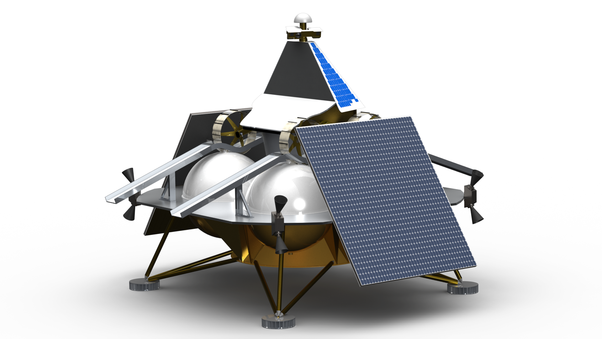
The focus of this project is the lander for the MoonCruiser mission in development at Carnegie Mellon University and Astrobotic Technology, Inc (See Figure 1). The lander has a single 4000N main engine for descent and orbit adjustment maneuvers and eight thrusters that provide actuation for the attitude control system (ACS). The ACS thrusters are located at the corners of the main lander deck, in four clusters of two.
Figure 1. Lunar lander for MoonCruiser mission
The ACS thrusters are canted to enable forces and torques in 6 degrees of freedom (DoF) using combinations of 4 thrusters. Figure 2 shows the cant angle from vertical, alpha. Figure 3 shows the cant angle in the yz-plane, beta. The angle between the thruster locations and the coordinate axes in the yz-plane is theta, which is nominally 45 degrees. The x-axis points down in the direction of main engine thrust.
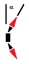
Figure 2. Cant angle from vertical
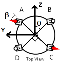
Figure 3. Cant angle in yz-plane
A positive force along the x-axis is accomplished by firing all of the upward-pointing thrusters, and likewise a negative force is accomplished by firing all the downward-pointing thrusters. A positive force along the y-axis is achieved by firing both the upward and downward-pointing thrusters at B and C (see Figure 3), and a negative force by firing thrusters at A and D. Forces along the z-axis are achieved by firing thrusters at D and C or at A and B. Torques about the y- and z-axes are achieved by firing both upward-pointing thrusters on one side of the spacecraft and both downward-pointing thrusters on the other side (see Figure 4). Torques about the x-axis are achieved by firing both the upward and downward-pointing thrusters at A and C or at B and D (see Figure 3 and Figure 5).
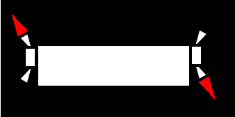
Figure 4. Thruster activation to achieve rotation about y- and z-axes
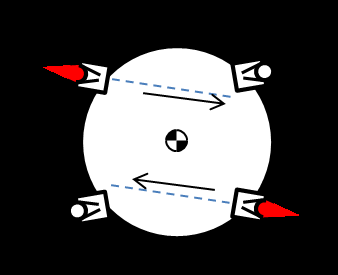
Figure 5. Thruster activation to achieve rotation about the x-axis
A PD quaternion controller has been implemented and run in simulation for a simple 16-thruster configuration (4 orthogonal thrusters at each corner of the lander, enabling actuation about each of 3 rotational degrees of freedom independently, or each of three translational degrees of freedom independently). The desired 8-thruster configuration with nominal cant angles of alpha = 30 degrees and beta = 30 degrees has also been implemented in simulation. Rotation about the x-, y- or z-axes or translational motion along the x-, y- or z-axes can be simulated, but the system cannot yet correct for error in more than one degree of freedom at a time.