Heather L. Jones (hjones@andrew) and Joseph Lisee (jlisee@andrew)
An attitude control system for a single-stage propulsive lunar landing spacecraft is developed and analyzed in simulation. The lander has one fixed, centrally located main engine and eight canted, pulsed attitude control thrusters capable of inducing motion in 6 degrees of freedom. Thruster selection strategies are examined for the case when correction is needed in multiple degrees of freedom. The control system performance is characterized for the maximum and minimum lander mass, and for an offset between the center of mass and the main engine line of action. The effects of system parameters such as thruster cant angles and minimum pulse width are also investigated.
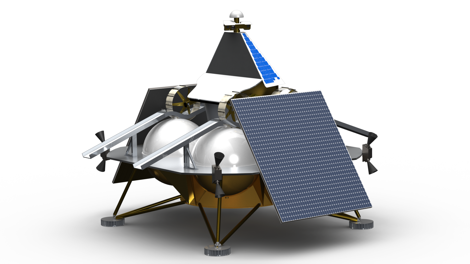
The focus of this project is the lander for the Lunar mission in development at Carnegie Mellon University and Astrobotic Technology, Inc (See Figure 1). The lander has a single 4000N main engine for descent and orbit adjustment maneuvers and eight 110N thrusters that provide actuation for the attitude control system (ACS). The ACS thrusters are located at the corners of the main lander deck, in four clusters of two.
Figure 1. Lunar lander for Astrobotic mission
Figure 2 shows the reference frame used for control superimposed on the lander.
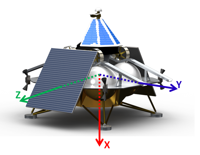
Figure 2. Control Frame
The ACS thrusters are canted to enable forces and torques in 6 degrees of freedom (DoF) using combinations of 4 thrusters. Figure 3 shows the cant angle from vertical, alpha. Figure 4 shows the cant angle in the yz-plane, beta. The angle between the thruster locations and the coordinate axes in the yz-plane is theta, which is nominally 45 degrees. The x-axis points down in the direction of main engine thrust.
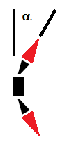
Figure 3. Cant angle from vertical
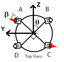
Figure 4. Cant angle in yz-plane
A positive force along the x-axis is accomplished by firing all of the upward-pointing thrusters, and likewise a negative force is accomplished by firing all the downward-pointing thrusters. A positive force along the y-axis is achieved by firing both the upward and downward-pointing thrusters at B and C (see Figure 4), and a negative force by firing thrusters at A and D. Forces along the z-axis are achieved by firing thrusters at D and C or at A and B. Torques about the y- and z-axes are achieved by firing both upward-pointing thrusters on one side of the spacecraft and both downward-pointing thrusters on the other side (see Figure 5). Torques about the x-axis are achieved by firing both the upward and downward-pointing thrusters at A and C or at B and D (see Figure 4 and Figure 6).
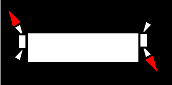
Figure 5. Thruster activation to achieve rotation about y- and z-axes
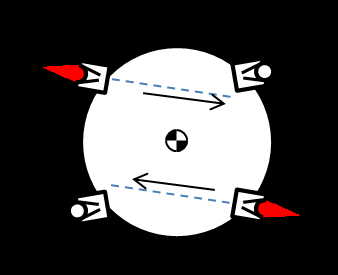
Figure 6. Thruster activation to achieve rotation about the x-axis
All of the thrusters on the lander are pulsed; each thruster is either all the way on, or all the way off. Pulse width modulation is used to achieve varying levels of thrust. The maximum impulse that can be applied per controller cycle is limited by the length of the cycle (or the period). The minimum impulse that can be applied is limited by the minimum pulse width, which results from the fact that there is a limit to how fast the thruster hardware can turn on and off.
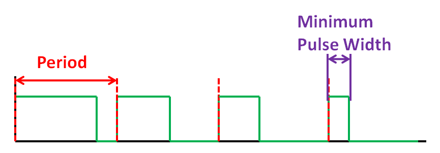
Figure 7. In pulse width modulation, the thruster on-time is varied between the minimum pulse width and 100% of the period
As thrusters are fired, they burn fuel, which decreases the mass of the lander. While the amount of fuel burned by the ACS thrusters over the course of an attitude maneuver is small, the amount burned by the main thruster over the length of the mission is quite significant. Thus, for the same thruster torque, very different rotational accelerations are produced depending on how much fuel remains.
Ideally, the center of mass (COM) of the lander will be centered at the center of the structure, and the moment-arms of the ACS thrusters will be balanced around the center of mass. However, it may not be possible to put the COM exactly where desired. The attitude control system must be able to handle some offset in the COM - the most important aspect of this is balancing any torque caused by firing the main engine when its line of action does not go through the center of mass.
Two different controllers were implemented: a simple PD controller and a more complex, parameterized phase plane controller.
For the PD controller, the error quaternion is computed from the current sensed attitude and the commanded target attitude. The percentage of maximum torque about each axis is then computed using the following control law:
 [1]
[1]
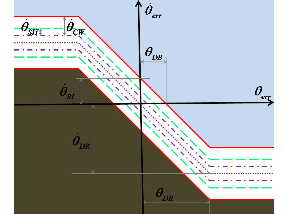
Figure 8. Phase plane controller for a single axis
In Johnson's approach, the error quaternion is computed from the current sensed attitude and the commanded target attitude. This quaternion is converted to axis-angle format. The angle is then compared against a maneuver threshold angle. If the angle is larger than the maneuver threshold, then the target rotational rate is set to -1 times a maneuver rate times the axis from the error orientation, the rate-error is calculated based on this command and the current sensed rate, and the angle-error is set to zero for all axes. This angle-error and rate-error are then passed into the phase plane controllers. If angle (of the axis-angle pair) is less than the maneuver threshold, then the target rates are zero and the target angles are the commanded target orientation converted to Euler angles. Each parameter of the phase plane controller (see Figure 8) can be set within bounds calculated from the physical parameters of the lunar lander and from previously set controller parameters.
Sets of four thrusters can be combined to produce torque about a single axis, as shown in Table 1. The difficulty is that the same thrusters are used in different combinations. One approach that can handle the need for torque about multiple axes is to partition each thruster's maximum activation into thirds, and reserve one third for motion about each axis. The per-axis activation commands can then be added together to get the total activation. Thus, if one thruster is needed in three axis-rotation combinations, it's total activation will be 100 percent of the maximum possible. This method allows the thruster selection for each axis to be treated independently.
Table 1. Thruster Selection
| Motion | Thrusters |
| +X Rotation | 1,2,5 and 6 |
| - X Rotation | 3,4,7 and 8 |
| +Y Rotation | 1,4,6 and 7 |
| - Y Rotation | 2,3,5 and 8 |
| +Z Rotation | 1,3,6 and 8 |
| - Z Rotation | 2,4,5 and 7 |
A second thruster selection method comes from the recognition that the information in Table 1 can be encoded into a matrix that maps thruster activations to torques. What is really desired is the inverse of this matrix, to take desired torques to thruster activations. The matrix is not square, so it does not actually have an inverse, but it does have a pseudo-inverse. When the pseudo-inverse is multiplied by a set of desired torques, it gives a set of thruster activations. Unfortunately, some of the calculated activations are negative, and a negative thruster activation time is not possible. This problem can be solved by finding the minimum negative activation value, and subtracting it from all of the activation values. The resulting activation vector produces the same torques as the previous calculated one containing negative values. It is also necessary to ensure that the commanded thruster activation is not larger than one. This is accomplished by thresholding on a per-thruster basis.
Common error metrics for control are overshoot and settling time. For a spacecraft, pointing error also matters (See Figure 9).
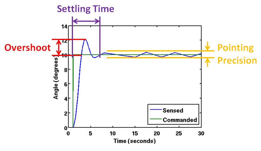
Figure 9. Error Metrics for Control
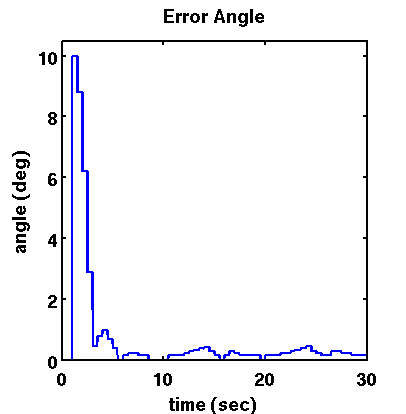
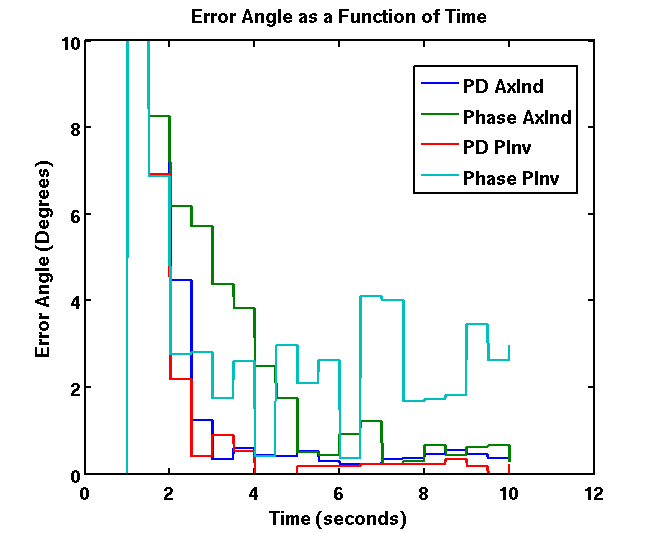
These metrics are harder to quantify, however, with a spacecraft spinning in three dimensions. Instead, the orientation error can be converted to axis angle format. The angle gives one number to track how far the spacecraft is from its target. This angle can then be integrated, accumulating the total error over time. Sidi calls this error metric "EULERINT" [1], but for the purposes of this project, it is simply called "badness". The "badness" captures the error accumulated from slow settling time, overshoot, or poor pointing precision.
 |
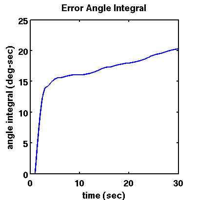 |
Figure 10. Error Angle and Integral of Error Angle ("Badness")
 |
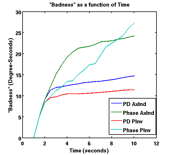 |
Figure 11. Comparing controllers and thruster selection methods. Each controller (PD and Phase Plane) is combined with each thruster selection method (Axis-Independent and Pseudo-inverse). The run time was cut to 10 seconds because the controllers were already at steady state error by that time.
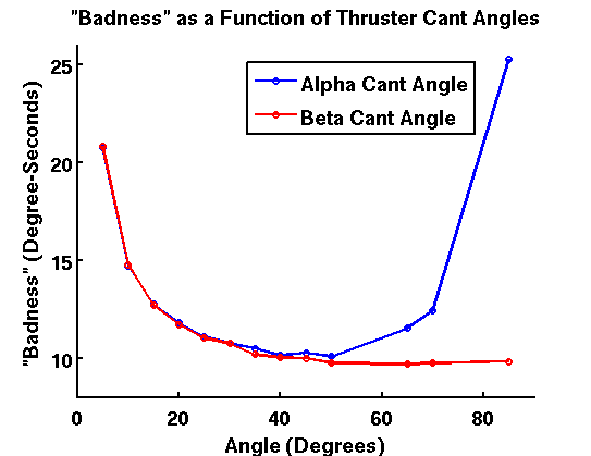
Figure 12. Comparing "badness" over varying thruster cant angles, using the PD controller with the axis-independent thruster selection method
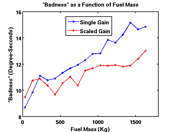
Figure 13. Comparing "badness" over varying spacecraft fuel mass values, using the PD controller with the axis-independent thruster selection method. The single gain line does not vary the PD controller gains with mass. The scaled gain line varies the gains linearly with fuel mass.
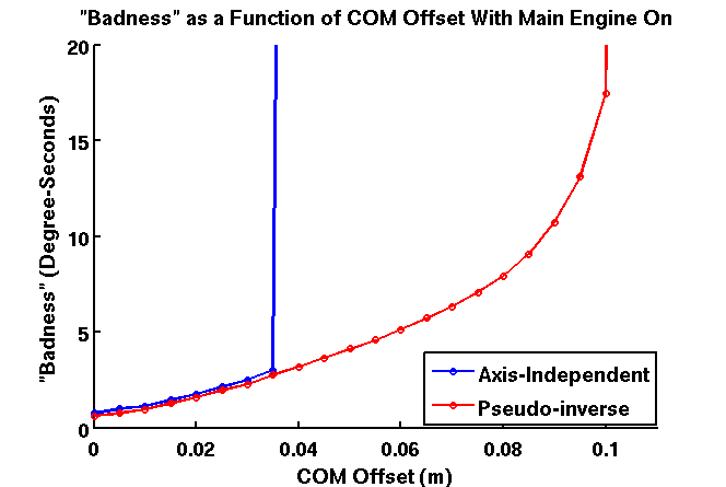
Using the thruster positions, directions and magnitudes, the maximum torque from a set of 4 thrusters about a given axis can be calculated. For the y and z axes, the maximum torque is 471.5 Nm. Given that the main thruster force is 4000 N, the distance between the main thruster line of action and the COM can be up to 0.11788 m off before the main thruster torque is greater than the maximum ACS torque. To keep the lander controlled under constant torque from the main thruster, the offset must be lower still. The plot below shows the performance of the PD controller under a range of COM offsets, with two different thruster selection methods.
From the comparison of controllers, the PD controller appears to be better. One caveat is that the PD controller has 2 parameters (gains) per axis to tune. The phase plane controller has 5 parameters per axis, plus two overall parameters (the maneuver threshold and maneuver rate). Thus, the phase plane controller is more difficult to tune and the performance shown may not be for the best selection of parameters.
For the PD controller, the pseudo-inverse method is clearly the better thruster selection method. This is not surprising, because the pseudo-inverse method does not restrict the controller to 1/3 of the total activation about a given axis so long as the total activation remains below 100%.
The comparison of thruster cant angles shows that there is an important dependence of controller performance on spacecraft configuration. The thruster cant angle also affects translational motions that can be actuated with the ACS thrusters, which was not evaluated here. Trade-offs would have to be made between torques and translational forces to choose the best cant angles.
The evaluation of varying mass shows that the controller needs to be tuned differently for different spacecraft masses. This could be accomplished with gain scheduling.
By varying the center of mass offset, we see that the PD controller with the pseudo-inverse thruster selection method handles main thruster torques quite well. The maximum offset for which the controller maintains control is close to the theoretical maximum (when the main thruster torque would overwhelm the ACS). The PD controller with the axis-independent method of thruster selection does not perform nearly so well.
[1] Sidi, Marcel J., "Spacecraft Dynamics and Control: A Practical Engineering Approach", Cambridge UP, 2006.
[2] Johnson, Michael C., "A Parameterized Approach to the Design of Lunar Lander Attitude Controllers", AIAA Guidance, Navigation, and Control Conference and Exhibit, Keystone, Colorado, 21 - 24 August 2006.
Code for this project can be found here.
For more on Carnegie Mellon and Astrobotic Technology's mission to the moon, visit the Astrobotic Technology Website.