 General Controller Board
We decided that commercial boards did not quite offer what we where looking for. We ended up designing a custom board to get the following functionality:
- Fast Main Processor that could spend most of its time on actual processing
- 8 Servo Outputs controlled by a dedicated PIC16F876
- 2 Channel of 2 amp H-Bridge output
- Dedicated hardware PID control done by another PIC16F876
- Low Power Consumption
- 2 115,200 baud serial ports (1 for the camera, 1 for debugging)
- 8 A/D inputs
- 8 misc I/O ports for jumpers etc
- A total cost of under $150 (But lots of work to build and no supporting software)
- 8 status LEDs
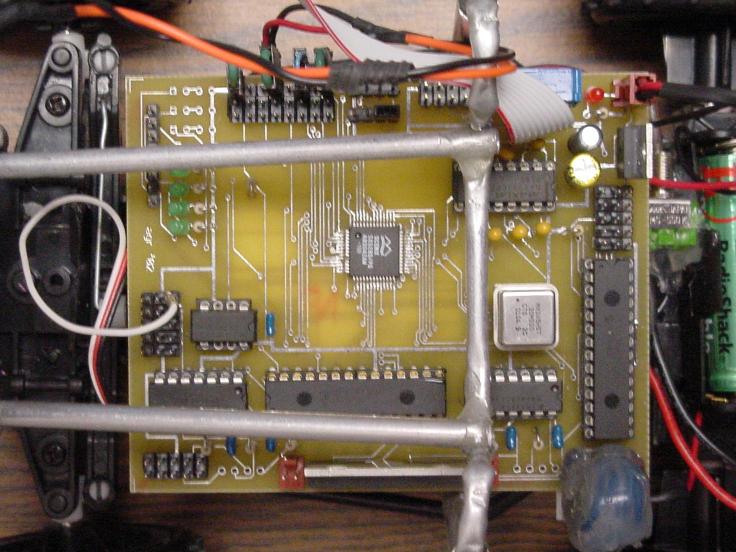
The board has the main SX52 processor which connects to the two PIC processors using an 8 bit wide, high speed data bus with two separate control lines. This allowed for easy high speed communication between the SX52 and the PICs. We wanted a high speed bus to insure that the SX52 was not being taxed by communication to its peripherals. Each PIC could then either act as a PID controller for a channel of the H-bridge, a servo controller, or misc I/O or data collector. The SX52 also had outputs for servo control in case you wanted high speed control over actuators from the main processing unit. We also had two optical encoder input ports for the PID control chips that used flip-flops to help reduce the counting load on the PICs. This helped reduce the cost of expensive encoder counter setups. The two serial ports are level shifted and then connected to the SX52 processor. This board was over kill by design because we wanted the flexibility to change our design as it evolved. It was relatively spread out to allow for easy future modifications, yet still fit on a 3 by 4 inch double sided board. See the Open Source Section for schematics and more construction details.
Main CPU
Our main microcontroller was a $8 Ubicom SX52 chip. The chip has 40 I/O pins 262 bytes of Ram, 4K of ROM and runs at 75 MIPS (can run at 100 MIPS). We used this controller because we wanted to insure that speed was not our limiting factor in keeping up with our image data. It lacks RAM and ROM which makes life difficult, but in the case of mobot we never reached these constraints.
Slave CPU's
Along with the SX52 we had two $7 PIC16F876 slave processors that we configured to either act as a servo controller, data collector or PID controller. The PIC16F876 has 368 bytes of RAM, 8K of ROM, 20 I/O pins and runs at 5 MIPS. These chips are easy to program and have built in A/D converters making them perfect work horses to do data collection, servo control and PIC motor control. Due to the chips slow clock speed and our need to have fast motor control loops, we used two flip-flops to take off the load of quadrature decoding by determining the direction of our encoder inputs. Communication to the slave chips was via an 8bit data bus with two eternal signal lines.
Power System
We wanted to run the mobot off of a single power source, but due to motor noise at lower voltages this turned out to be more of a pain than it was worth. We ended up having the motor powered by 7.2 volt RC car battery mounted on the frame above the controller board. The electronics where powered by 5 AA NiMH batteries that where located on the bottom and back of the body. This combination gave us great run time life and the ability to expand motor voltage for extra speed. To avoid voltage fluctuation problem we added a large capacitor and a small capacitor to the main power before going into the controller boards regulator (always a good idea to have lots of caps).
Mobot Body
The body of our mobot is a modified $20 RC Jeep. We replaced its solenoid steering with a Futaba micro-servo to allow for more fine steering control. This modification was surprisingly easy because the servo fit well into the steering compartment of the car. We also replaced the car's motor with a Maxon A-max motor with ironless core and AlNiCo magnets. (Motor Data Sheet part number 110156 with precious metal brushes). We had a 12 counts per turn, 2 channel, Digital Magnetic Encoder attached. (Encoder Data Sheet) We hollowed out the gear box area of the RC car to make room for the slightly larger motor. We also moved the original gear from the car onto our new motor to maintain a good connection. Loctite glue is your friend when it comes to things like this... The supporting frame above the motor board is made out of bent thin aluminum pipe glued together with epoxy.
The Camera
Finally, we used a CMUcam vision sensor as our main form of navigational input. The CMUcam is an embedded vision system that can be purchased for $109 that does color object tracking at 17fps. We used the camera in streaming line mode which allowed us to get a binary image of the line 17 times a second. We then used this image to calculate the slope of the line and determine when we had reached decision points. See our firmware section for more details.