Radiant Panels for Heating/Cooling
Radiant panels in the Intelligent Workplace are used for heating/cooling purposes. Radiant ceilings are continuously suspended ceilings that operate according to the radiation principle. The panels may be either linear or modular with flat, grooved, or channeled surfaces. Linear panels are generally either extruded aluminum or steel heating strips in 1- to 2-ft widths and lengths to approximately 16 ft. The individual panels can be fastened together by brackets or be formed as tongue-and-groove units to form panels of the length and width required. Modular panels utilize similar framing that facilitates recess mounting in gypsum or T-bar grid ceiling systems.
The face of the metal panel is the radiating surface to which the heat is conducted from the copper tubing that is routed through heat transfer channels. The tubing is mechanically held in direct contact with the back of the panel plank or
trays to facilitate heat conduction. Hot/cold water is circulated into these copper tubes according to the required indoor temperature.
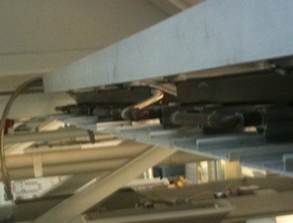
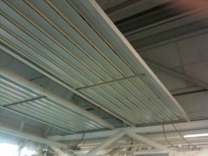
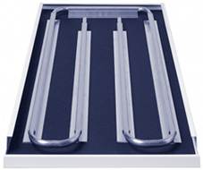
View of the radiant panels in the IW
In the IW, during winter, the system is turned on during the early morning hours (4am-9am) to meet the indoor set point temperature. Once the indoor temperature is met, the system is turned off. During summer, the panels are used for cooling purposes. The system is turned on when the indoor temperature rises above 65 F.
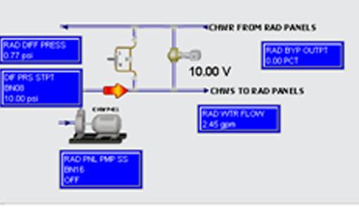
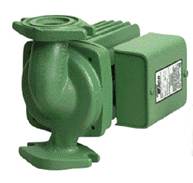
Schematic Diagram of the water pump, flow rate valve for the radiant panels
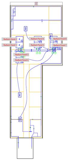
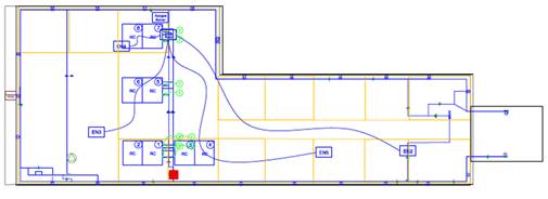
Plan indicating the location of the radiant panels in the IW
Assembly of Radiant Panels:
The overhead panels in Figure xx are made of two aluminum panel pieces. Two pieces of panels are connected by a U-shaped tube to form one module. One panel is approximately 7ft long, and one module is approximately 14ft long (two panels). Fig xxb shows a detail of the connection of the coil and the aluminum panel on a Trox radiant panel. The pipe is a 0.5 inch nominal diameter copper tube and the width of each panel is about 8 inches. Hot/cold water is circulated in these copper pipes. The pipes are well insulated to avoid temperature loss.
View of the water pipes supplying hot/cold water to heat/cool the aluminum panels
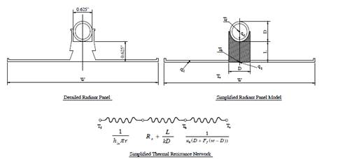
Mathematical model for radiant panels
The process of heat transferring from the radiant panel to the indoor space can be separated into two parts: (1) heat transferred from the root section, shown in equation 2, where the heat flow component is given by ![]() as shown in equation 1, and (2) the heat transferred by the fin section,
as shown in equation 1, and (2) the heat transferred by the fin section,![]() , as shown in equation 1.
, as shown in equation 1.
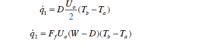 ………………………………………………..…………….equation 1
Tais the air temperature,Tbis the temperature, Ffis the fin heat transfer coefficient, which can be calculated from the formula specified in equation 2.
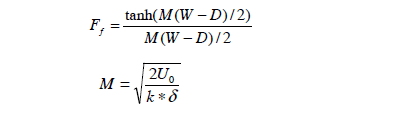 ………………………………………………………………equation 2
From the above equations, the total heat transfer can be calculated using the equation 3.
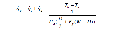 ………………………………………………………………equation 3
The heat transferred from the water to the radiant panel can be determined using the water-side resistance, the contact resistance and conduction resistance using equation 4.
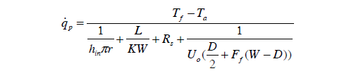 …………………………………………..equation 4
The heat transferred from the radiant panel can be expressed by means of an efficiency factor F1, which is given by the ratio of the overall heat transfer from the fluid and the overall heat transferred to the room from the fins, which is given by equation 5.
![]() ……………………………….……………………………………………….equation 5
……………………………….……………………………………………….equation 5
The factor F1 is determined by equating equation 4 and 5 which is given by the following equation:
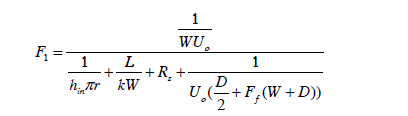 ……………………………………………………………..equation 6
Components of Radiant panels
Components of Radiant panels
Device type |
Pump (Cartridge Circulator) |
Device ID |
Water pump for radiant panels |
Manufacturer |
TACO Incorporated |
Model |
0011 – F4 |
Part Number |
N/A |
Installation date |
1997/1998 |
|
|
Device type |
Siemens Actuator |
Device ID |
Actuator valve for radiant panels |
Manufacturer |
Siemens |
Model |
SSA61U |
Part Number |
N/A |
Installation date |
March/April 2011 |
|
|
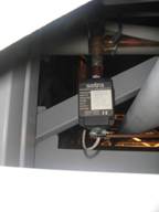
Device type |
Setra Pressure Transducers |
Device ID |
Differential Pressure Transducers for Radiant panels |
Manufacturer |
Setra |
Model |
206/207 |
Part Number |
N/A |
Installation date |
March/April 2011 |


Device type |
Pump (Cartridge Circulator) |
Device ID |
Water pump for radiant panels |
Manufacturer |
TACO Incorporated |
Model |
0011 – F4 |
Part Number |
N/A |
Installation date |
1997/1998 |
|
|
Device type |
Siemens Actuator |
Device ID |
Actuator valve for radiant panels |
Manufacturer |
Siemens |
Model |
SSA61U |
Part Number |
N/A |
Installation date |
March/April 2011 |
|
|
Device type |
Setra Pressure Transducers |
Device ID |
Differential Pressure Transducers for Radiant panels |
Manufacturer |
Setra |
Model |
206/207 |
Part Number |
N/A |
Installation date |
March/April 2011 |