Thermal 5: 3D Heat
Conduction within a Solid
Introduction:
In this example you
will learn to build and assess #3D geometries in heat transfer by
modeling an object subjected to requirements and specific boundary
conditions. Using ANSYS will allow you to output the temperature
distribution in an extremely simple and accurate way.
Problem Description:
·
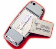
We
assume that our phone is a rectangular solid, with filleted corners as
they appear in the image.
·
All
units are S.I.
·
Boundary Conditions:
2) All faces except that of the battery have convective boundary
layers.
3) The battery generates heat at a rate of 50 W/m^2/s.
5)
Heat is uniformly generated in the bock at a rate of 20 W/m^2.
·
Material Properties: (Steel)
h =
50 W/(m^2*K)
k(innards)
= 10 W/m-K
k(lithium) = 84.8 W/m-K
k(plastic) = 0.18 W/m-K
·
Objective:
To determine the nodal temperature
distribution and create contour plot.
·
Dimensions
1.
Cellphone: 0.1143m
long x 0.0254m thick x 0.0508m wide
(4.5 inch x 1 inch x 2 inch )
2.
Battery:
Length: 50.8
millimeters Thickness: 10.16 millimeters Width 38.1
millimeters (2 inch x 0.4 inch x 1.5 inch)
Note that the actual
dimensions of the battery are: Length: 53 millimeters Width 37
millimeters Thickness: 10 millimeters (2.087 inch x 1.457
inch x 0.3937 )
We will use
approximations because the heat transfer will still display the same
general distribution
Note: For any
necessary conversions, this site is useful:
http://www.convert-me.com/en/convert/length


The dimensions of the
drawing are in English because the specs of the phone given on the web
are in English (making the CAD drawing easier to build in English)
REMEMBER TO CODE
ANSYS WITH SI, not English
Note: .1 inch =
2.54 mm
Also, R0.50in =
0.0127m
Starting ANSYS:
·
Click
on
ANSYS
6.1
in the
programs menu.
·
Select
Interactive.
·
The
following menu comes up. Enter the working directory. All your files
will be stored in this directory. Also under
Use
Default Memory Model
make
sure the values
64
for Total Workspace, and
32
for Database are entered. To change these values unclick
Use
Default Memory Model.

·
Click
RUN
Modeling the
Structure:
·
Go to
the ANSYS Utility Menu (the top bar)
·
Click
Workplane>WP Settings…
·
The
following widow comes up:
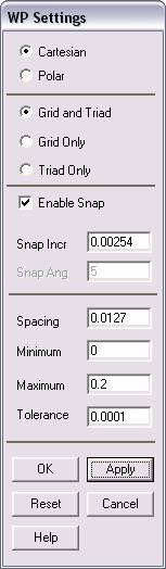
·
Check
the Cartesian and
Grid and Triad Only buttons
·
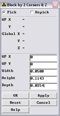
The
first step is to create the inner volume to represent the space in the
phone that is occupied by the microchips and transistors.
·
Enter
the values shown in the figure above and then click OK. Note that
we are using a spacing increment of .1 inches or 2.54 millimeters. This
will help in a modeling step.
·
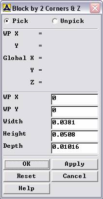
Go to
the ANSYS Main Menu (on the left hand side of the screen) and click
Preprocessor>Modeling>Create>Volumes>Blocks>By 2 Corners and Z
·
The
following window comes up:
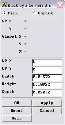
·
Enter
the values as shown and click OK.
·
Now
change the view to isometric mode, using
Menu>Plot Controls>Pan Zoom Rotate and by clicking the ISO
button. The plot should have zoomed to the new part.
·
Now you
have created the external phone. If at any time you cannot see the
complete Workplace then go to Utility
Menu>Plot Controls>Pan Zoom Rotate and zoom out to see the
entire Workplace. If you want to see the grid itself, go to
Utility Menu>Workplane>Display Working Plane
·
The
next step is to create the outer volume.
·
Go to
Utility Menu>Workplane>Offset WP by
increments and click these buttons to offset the workplane by
-.1 inches in each direction. This will enable you to create the inner
volume easily.
·
Next
use
Preprocessor>Modeling>Create>Volumes>Blocks>By 2 Corners and Z
again and this time enter the following:
Note that these
dimensions are simply the previous ones, minus 0.00508 which is .1x2
inches.
·
If you
messed something up, remember not to select Pick All when
deleting anything now, since you don’t want to destroy the model of the
inner volume.
·
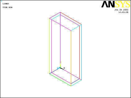
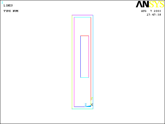
The
model should look like this now if you plot lines (Utility
Menu>Plot>Lines)and dynamically rotate the solid(Utility
Menu>PlotCntrls>Pan Zoom Rotate): (note, you have a black
background)
·
The
next series of steps involves creating the volume for the battery.
·
First,
use Offset WP by increments and increment the Workplane by two
positive increments in the Z direction. Next, change the snap
and grid increments of the workplane settings to 0.0381 m (1.5
inches, the distance between the bottom of the phone and the beginning
of the battery). Use Offset WP and offset in the Y direction by
one positive increment. Next, change the increments once
more to 0.00635 m (0.25 inches). Displace the WP in the X
direction one positive increment.
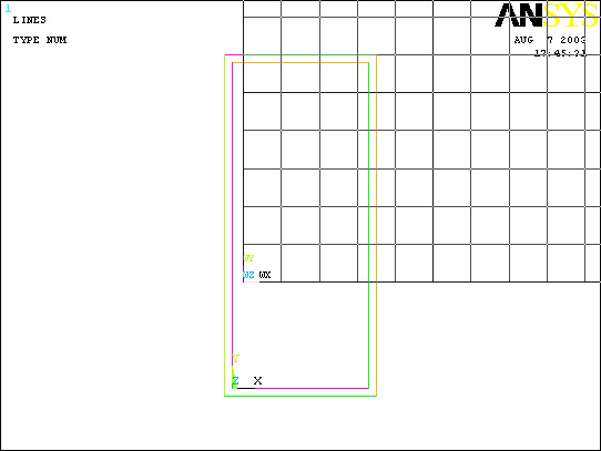
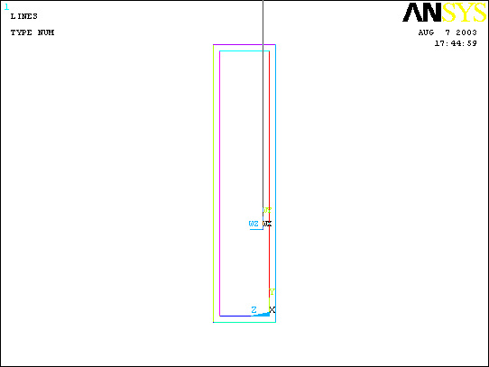
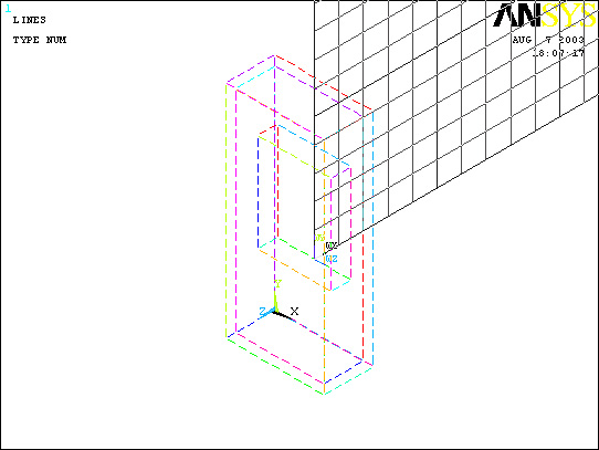
·
The
workplane will appear here: Note that The Pan Zoom Rotate settings here
are “Front” instead of ISO and only the lines are plotted: Basically,
the image should look like the CAD drawing from the top of the tutorial,
and the bottom corner is where the battery will be referenced from.
·
Now
create the volume for the battery:
·
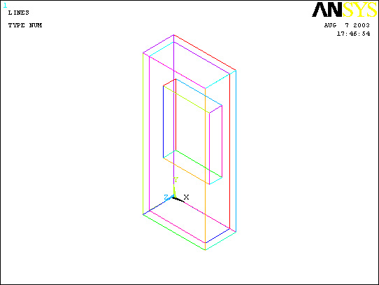
The
completed model will look like this: (note that I did not replot the
volumes because we wouldn’t be able to see any of the inner volumes!
And in ISO mode
·
One
final step that needs to be executed involves explaining that the
volumes overlap each other, so that when meshing, the volumes are
separate from each other. This is accomplished by choosing
Preprocessor>Modeling>Operate>Overlap>Volumes
·
First
select the outside layer and the inside layer (not the battery!) and hit
Apply. Then select the inside volume and the battery and hit OK. This
should resolve all the volumes. You can test this but plotting lines and
then trying the step again, the volumes should each be selected
separately… if so, then hit cancel and move forward.
Material Properties:
·
Now
that we have built the model, material properties need to be defined
such that ANSYS understands how heat travels through this composite
solid.
·
Go to
the ANSYS Main Menu
·
Click
Preprocessor>Material Props>Material Models.
·
The
pop-up window will now look like this:
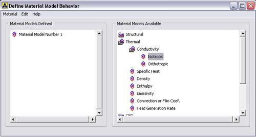
·
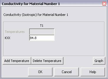
In the
window that comes up choose
Thermal>Conductivity>Isotropic.
(Double click Isotropic). The following window comes up:
·
Fill in
84.8 for Thermal conductivity. This defines the conductivity of
Lithium and correlates material 1 with it. Click
OK.
·
Choose
Define
Material Model Behavior>Material>New Model
and define another conductivity for the new model, that of the
innards (10 W/m K) and then repeat to define the Plastic case of the
phone (0.18 W/m K)
·
Now
exit the “Define Material Model Behavior” Window
Element Properties:
·
Now
that we’ve defined what material ANSYS will be analyzing, we have
to define how ANSYS should analyze our block.
·
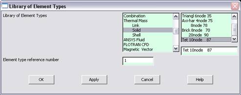
Click
Preprocessor>Element Type>Add/Edit/Delete...
In the 'Element Types' window that opens click on Add...
The following window opens:
·
Type
1 in the Element Type reference number.
·
Click
on Thermal Mass Solid and select Tet 10node 87. Click
OK.
Close the 'Element types' window.
·
Now we
have selected Element Type 1 to be a Thermal Solid 10node
Element. This finishes the section defining how the part is to be
analyzed.
Meshing:
·
This
section is responsible for telling ANSYS how to divide the block such
that it has enough nodes, or points, to analyze to make an accurate
enough analysis.
·
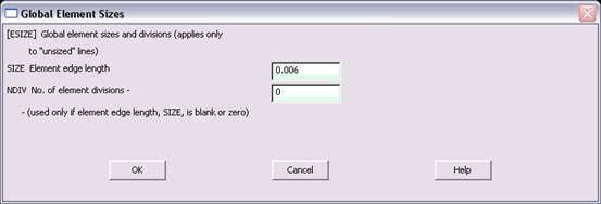
Go to
Preprocessor>Meshing>Size Controls>Manual Size>Global>Size.
In the menu that comes up type 0.006 in the field for ”Element
edge length”.
·
Click
on
OK.
Now when you mesh the figure ANSYS will automatically create square
meshes that have an edge length of 0.006m along the lines you
selected.
·
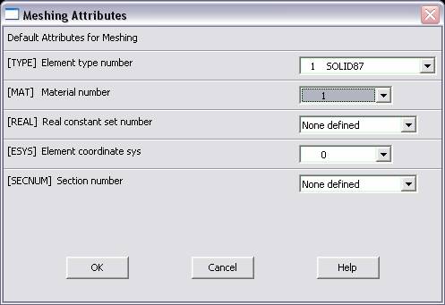
Now go
to
Preprocessor>Meshing>Mesh Attributes>Default Attributes.
The window is shown below:
·
Here
you finally put together material model and material type. Select the
appropriate material to mesh (first 1, lithium, as defined in the
Material Properties section) and pick what element type to use (selected
by the Element Type Number). Once this has been verified,
Click OK and proceed to
Preprocessor>Meshing>Mesh>Volumes>Free
·
A popup
window will appear on the left hand side of the screen. This window
allows you to select the area to be meshed.
·
Click
anywhere within the lithium battery you created to select the volume and
then click
OK
in the pop-up window.
·
Return
to Default Attributes and this time, select Material Number 2, to
model the innards of the phone.
·
Finally, choose material 3 and mesh the plastic casing.
·
The
model should now look like this:
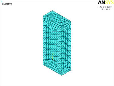
ISO
ELEMENTS
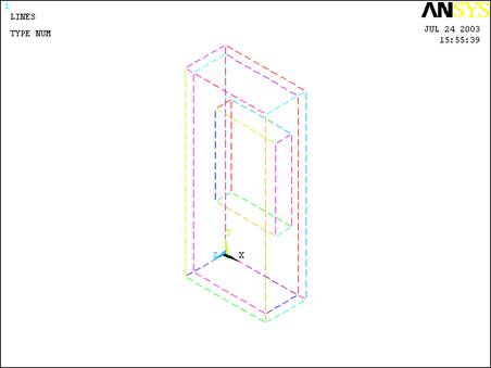
ISO
LINES
Boundary Conditions
and Constraints:
·
Now
that we have modeled the phone and defined how ANSYS is to analyze it we
will apply the appropriate Boundary Conditions.
·
Go to
Preprocessor>Loads>Define Loads>Apply>Thermal
(from here one can apply any of the loads, or Boundary Conditions,
offered by ANSYS.)
Apply
Convection (Case)
·
First
we’ll apply the Convection Boundary layer around the model. For this
click Convection>On Areas within
the Thermal Load category.
·
A
dialog window will appear on the left hand side of the screen. This
window allows you to select the areas you wish the load to be applied.
·
Select
the outside areas of the phone and click OK.
The following window will appear:

·
Fill in
the h value in the Film Coefficient blank and the Air
temperature in the Bulk Temperature blank. Click
OK when finished.
Apply Heat Generation
·
The
next step is to add the constraint of heat generation.
·
Preprocessor>Loads>Define Loads>Apply>Thermal>Heat Generat>On Areas.
(Heat Generat is just short for Heat Generation). You select Areas
again because you have to apply this condition uniformly across the
block.
·
Click
anywhere within the area to select it and then click
OK.
·
The
voltage of the battery is rated as 3.7V and the internal resistance is
on the order of 200 milli ohm. Therefore, the total power is I2R
= 2.738 W which break down to (V = 0.0000196644768 m3) =
139235.843 W/m3
·
Enter
139235.843 W/m3 as the heat generation value in
the pop-up window that appears:

·
Now we
have applied all the necessary boundary conditions so we move on to the
Solution.
Solution:
·
Go to
ANSYS
Main
Menu>Solution>Analysis Type>New Analysis.
·
Select
Steady
State
and click on
OK.
·
Go to
Solution>Solve>Current LS.
·
An
error window may appear. Click
OK
on that window and ignore it.
·
Wait
for ANSYS to solve the problem.
·
Click
on
OK
and close the 'Information' window.
Post-Processing:
·
This
section is designed so that one can list the results of their analysis
as a nodal solution
·
Go to
the ANSYS Main Menu. Click
General
Postprocessing>List Results>Nodal Solution.
The following window will come up:
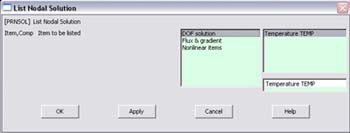
·
Select
DOF
solution
and
Temperature.
Click on
OK.
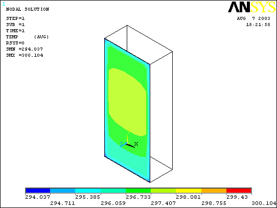
The nodal temperatures will be listed as follows:

·
Within
this window one can numerically find the maximum and minimum value of
the temperature within the block.
Modification /
Plotting the Results:
The last section
displayed the numerical results, but most analyses will require a plot
of the temperatures on the block in addition to the numerical results.
This is how you go about doing that…
·
First
go to
Utility Menu>PlotCtrls>Style>Hidden Line Options
·
The
following window appears. Choose Q Slice Z Buffer and Working
plane as shown below

 |
Now there will be a
cross section shown of the temperature distribution in the direction
of the workplane. Try rotating the workplane so that this slice is
shown (you may want to replot lines): |
|
To see the
workplane, return to
Utility Menu>Workplane>WP Settings…
and choose Grid and Triad |
|
Then use
Workplane>Offset WP by increments
and use offset by angles (change increments to 90 degrees) Offset in
the +Y direction 90 degrees, then by 3 snap increments in the +Z
direction. Should look something like this: |
Choose
General
Postprocessing>Plot Results>Contour Plot>Nodal Solution.
The following window will come up:
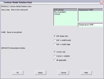
|
Check the entries
and hit OK. The result should be something like below! |
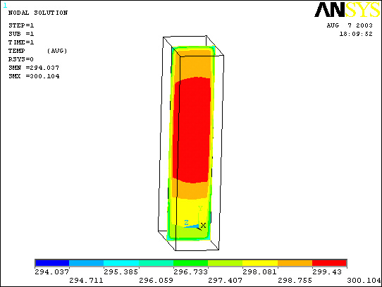
ISO
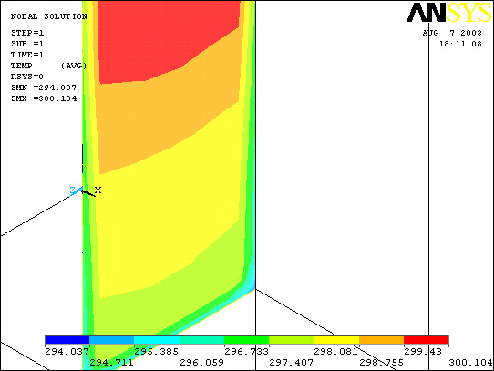
ISO
zoomed in on bottom
Now offset the WP
back to the original angle (rotate in the –Y direction by 90 degrees)
and then choose Utility Menu>Workplane>Offset
WP to>Global Origin. Change the WP settings to 0.02261 and
offset the WP once more by 1 snap increment in the +Z direction. If you
replot the contour, you can see that the temperature of the phone near
the ear will be on the order of 296 K which is 73.13 degrees Fahrenheit.
Some people might find that uncomfortable. This of course, is a crude
model of the phone as most of us with phones have experienced more
discomfort. Note that the phone is also warmer in the middle area,
directly across from the battery…which is sensible and also more likely
to be noticed in general.