Thermal #4: Temperature
distribution in a 3D fin cooled electronic component
Introduction:
In this
example you will learn to model a cooling fin for electronics. This
involves heat generation, conduction and convection.
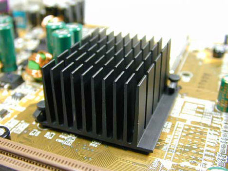
Physical Problem:
All
electronic components generate heat during the course of their
operation. To ensure optimal working of the component, the generated
heat needs to be removed and thus the electronic component be cooled.
This is done by attaching fins to the device which aid in rapid heat
removal to the surroundings.
Problem Description:
 |
For the sake of
simplicity we assume that the electronic circuit is made of copper
with thermal conductivity of 386 W/m K. Also it generates heat at the
rate of 10e6 W. |
|
The enclosing
container is made of steel with thermal conductivity of 20 W/m K.
|
|
The fins are made
of aluminum with thermal conductivity of 180 W/m K. |
|
Units: Use
S.I. units … centimeters ONLY |
|
Geometry:
See figure. Please note that the heat generating copper is only 3
cm long, and does not extend to the end of the base! |
|
Boundary conditions:
There is convection along all the boundaries except the bottom, which
is insulated. The Film Coefficient is 50 W/m2K and the Bulk
Temperature is 20oC. |
|
Objective:
 |
To determine the
nodal temperature distribution. |
|
To determine the
maximum value of temperature in the component. |
|
|
You are required to
hand in print outs for the above. |
|
Figure:
|
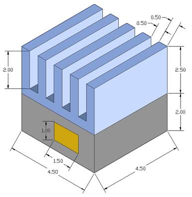
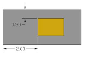
Front
View of Heat Generating base
PLEASE NOTE THAT THE COPPER IS ONLY 3cm in depth
(or in length)
IMPORTANT:
Convert
all dimensions and forces into SI units.
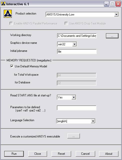
STARTING ANSYS
Click
on ANSYS 6.1in the programs menu.
Select
Interactive.
The
following menu that comes up.
Enter the working directory. All your files will be stored in this
directory. Also enter 64 for Total Workspace and 32 for
Database.
Click
on Run.
MODELING THE STRUCTURE
|
Go to the ANSYS
Utility Menu.
|
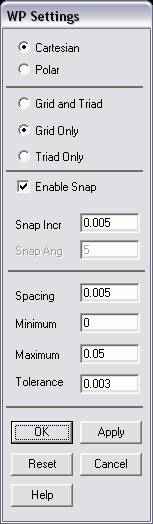
Click
Workplane>WP
Settings.
|
|
The following
window comes up |
|
|
Check the
Cartesian and Grid Only buttons. |
|
Enter the values
shown in the figure below. |
|
Select
Workplane>Display
Working Plane |
|
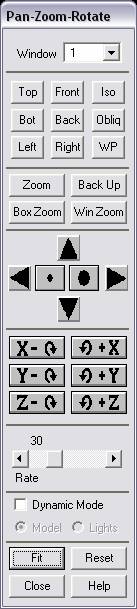
Now use
Utility Menu>Plot Controls>Pan Zoom Rotate
and use the following window to select iso
mode and translate and zoom the working plane to an appropriate
viewing distance |
|
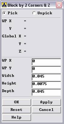
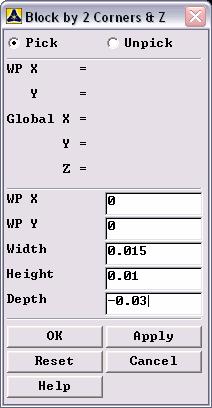
Go to the ANSYS
Main Menu
Preprocessor>Modeling>Create>Volumes>Block>By 2Corners and Z.
|
|
The following
window comes up: |

|
Enter the following
data values to create the full steel base of the heat generating
volume. |
|
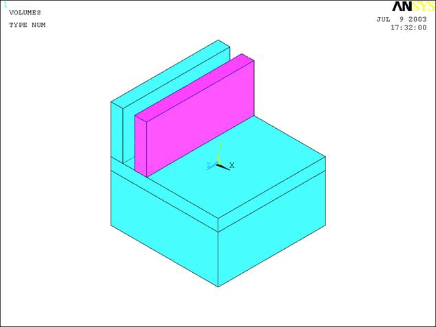
Continue by making
the fin assembly in sections, first creating a “base” section and then
by making one fin. |
|
This is what it
should appear like after you create these three volumes: |

|
Now we want to copy
the fin volume and paste it offset so that it is correctly positioned
along the bottom of the fin assembly. |
|
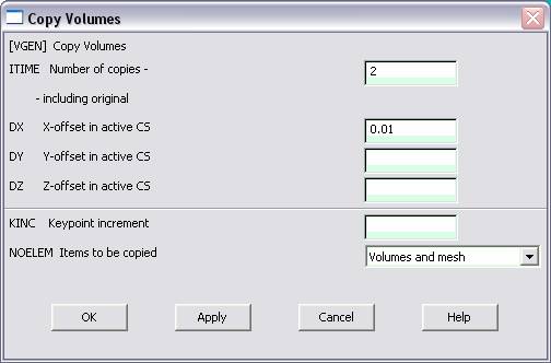
Preprocessor>Modeling>Copy>Volumes
Select the volume to be copied. Next, the following window appears:
|
|
Enter the value for
the offset, which is 1 cm and then click OK. Next, choose
Preprocessor>Modeling>Copy>Volumes
again and select the new volume. See below |
|
All you have to do
is enter the same offset, since you are using the new fin..
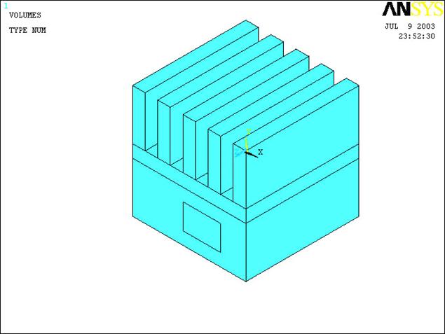
Repeat the process until all the fins are created. This is how
everything should appear: |

|
Next choose
Preprocessor>Modeling>Operate>Booleans>Add>Volumes.
Choose the fins and bottom of the fin assembly (the thin layer that
extends across the model) Hit OK |
|
Next, glue the new
completed fin assembly to the base, by using
Preprocessor>Modeling>Operate>Booleans>Glue>Volumes.
Choose the base, and click once on the fin assembly (it should all be
selected as one now, if not try repeating the last step). Hit OK
|
|
Now, create the
volume for the copper heat generating element. One effective method is
to use
Utility Menu>Workplane>Offset WP by
increments
Then offset the
work plane (use Pan Zoom Rotate to adjust both the zoom and the
perspective of the block, using iso
and front can be effective) until the
workplane is flush with the front of the model and lined up as
show below: |
|
Go to the ANSYS
Main Menu
Preprocessor>Modeling>Create>Volumes>Block>By 2Corners and Z
|
|
This time when the
window appears, you can enter |
|
The last step is to
use
Preprocessor>Modeling>Operate>Booleans>Overlap
and select the copper volume and the steel, click OK. |
|
The modeling is now
finished. The model should look like the one below. |
MATERIAL PROPERTIES
|
We need to define
material properties separately for steel, aluminum, and copper.
|
|
Go to the ANSYS
Main Menu |
|
Click
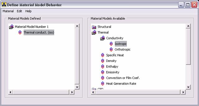
Preprocessor>Material Props>Material Models.
In the window that comes up choose
Thermal>Conductivity>Isotropic.
|
|
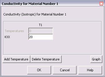
Enter 1 for the
Material Property Number and click OK. The following window comes up.
|
|
Fill in 20
for Thermal conductivity. Click OK. |
|
Now
the material 1 has the properties defined in the above table. This
represents the material properties for steel. Repeat the above
steps to create material properties for aluminum (k=180,
Material number 2), and copper (k=386, Material number 3). Do
this by selecting
Material>New Model
in the “Define
Material Model Behavior” window. Once finished, exit the material
model window. |
ELEMENT PROPERTIES
|
SELECTING ELEMENT
TYPE: |
|
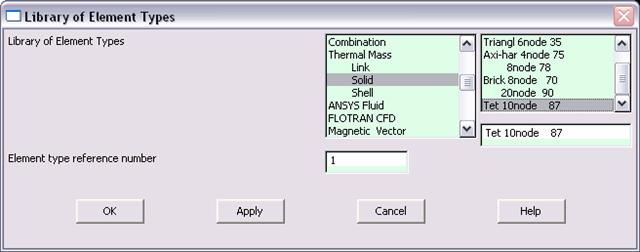
Click
Preprocessor>Element Type>Add/Edit/Delete...
In the 'Element Types' window that opens click on Add... The following
window opens. |
|
Type 1 in
the Element type reference number. |
|
Click on Thermal
Mass Solid and select Tet
10node 87. Click OK. Close the 'Element types' window. |
|
So now we have
selected Element type 1 to be a thermal solid 8node element. The
component will now be modeled with thermal solid 8node elements. This
finishes the selection of element type. |
MESHING
|
DIVIDING THE TOWER
INTO ELEMENTS: |
|
Go to
Preprocessor>Meshing>Size Controls>Manual Size>Global>Size.
In the menu that comes up type 0.005 in the field for 'Element
edge length'. |

|
Click on OK. Now
when you mesh the figure ANSYS will automatically create meshes that
have an edge length of 0.005m along the objects you selected.
|
|
First we will mesh
the steel area. Go to
Preprocessor>Meshing>Mesh Attributes>Default Attributes.
Make sure the window indicates "Material Ref.#1".
The window is shown below. |

|
Now go to
Preprocessor>Meshing>Mesh>Volumes>Free.
Pick the steel area and click OK. |
|
After you mesh the
first section, the plot function of ANSYS may only display that meshed
solid. To reveal the other solids, use
Utility Menu>Plot>Volumes.
Even though the already meshed area appears like it did originally, it
is STILL meshed! Continue to the next steps. |
|
Repeat the same
process for the aluminum and copper areas. Make sure you use the
correct material number (2 and 3 respectively) for both the areas.
Also since the steel and the copper areas overlap make sure you pick
the right area. If you choose the wrong area, use
Preprocessor>Meshing>Clear
to undo the previous mesh and then repeat the previous steps. The
meshed area should look like this: |

FRONT
ISOMETRIC
BOUNDARY CONDITIONS AND
CONSTRAINTS
|
Go to
Preprocessor>Loads>Define Loads>Apply>Thermal>Heat Generate>On Areas.
|
|
Select the areas of
the copper square. Click OK. The following window comes up.
|

|
Enter 1e7
for the HGEN value and click OK. |
|
Go to Preprocessor>Loads>Define
Loads>Apply>Thermal>Convection>On Areas.
|
|
In ISO viewing
mode, pick the areas that are clearly visible and don’t try to pick
them all (all twenty something areas of the fin assembly) at once.
Make notes in a text file if you want to keep track of what you have
selected already (such as fins, front, iso
or fins, top iso and so on) Click OK. The
following window comes up. |
|
Just remember that
you want to select the aluminum assembly areas, which mean the fins
sticking out and the thin bottom of the aluminum assembly. Remember
not to pick the bottom side of it too..
because that section is exposed to heat,
not convection. |
|
For each convection
… apply the following values: |

|
Enter 50 for
"Film Coefficient" and 20 for "Bulk Temperature" and click OK.
|
|
Now the Modeling of
the problem is done. |
SOLUTION
|
Go to ANSYS
Main Menu>Solution>Analysis Type>New Analysis.
|
|
Select Steady
State and click on OK. |
|
Go to
Solution>Solve>Current LS.
|
|
An error window may
appear. Click OK on that window and ignore it. |
|
Wait for ANSYS to
solve the problem. |
|
Click on OK and
close the 'Information' window. |
POST-PROCESSING
|
Listing the
results. |
|
Go to ANSYS Main
Menu
General Postprocessing>List Results>Nodal
Solution.
The following window will come up. |

|
Select DOF
solution and Temperature. Click on OK. The nodal
displacements will be listed as follows. |

|
You will find the
maximum value of temperature at the end of the above table.
|
MODIFICATION
|
You can also plot
the displacements and stress. |
|
Go to
General Postprocessing>Plot
Results>Contour Plot>Nodal Solution.
The following window will come up: |

|
Select DOF
solution and Temperature to be plotted and click OK. The
output will be like this:
(playing with Pan
Zoom Rotate) |

FRONT VIEW
ISO
BOTTOM VIEW (dynamically rotated)
Rotated back and bottom view
|
|