Structural #2: Analysis
2-D Beam structure
Introduction:
In this
example you will learn to use the 2-D Beam element in ANSYS.
Physical Problem:
Structural analysis of the frame shown below.
Problem Description:
 |
The structure is
made up of beams. You may recall that a beam is a structural element
whose length is very large compared to the other two dimensions.
|
|
Units: Use S.I.
units ONLY |
|
Geometry: The
members have a annular cross-section. The
cross sections (A) of each of the truss members is
5.5e-3 sq meter. The polar radius of gyration (R) is 5.5e-2 meter.
(hint: Use the values of A and R to find Izz
then find the value of the outer diameter (The beam height))
|
|
Material: Assume
the structure is made of steel with modulus of elasticity E=210
GPa.
|
|
Boundary
conditions: All the DOFs are constrained
at the bottom end, i.e. the bottom end is a built-in end. |
|
Loading: The
structure is loaded at the ends of the two arms. The load is in the
negative Y direction. The load value is 5000 N each. |
|
Objective:
 |
To determine
deflections at the points of application of load. |
|
To determine the
maximum stress in the structure. |
|
Also determine
the maximum possible load the frame can take. Look up for the value
of yield stress for steel. Assume a factor of safety of 1.25.
|
|
|
You are required to
hand in print outs for the above. |
|
Figure: |
IMPORTANT:
Convert
all dimensions and forces into SI units.
STARTING ANSYS
|
Click on ANSYS 6.1
in the programs menu. |
|
Select Interactive.
|
|
The following menu
that comes up. Enter the working directory. All your files will be
stored in this directory. Also enter 64 for Total Workspace and 32 for
Database. |
|
Click on Run.
|
MODELING THE STRUCTURE
|
Go to the ANSYS
Utility Menu |
|
Click
Workplane>WP
Settings |
|
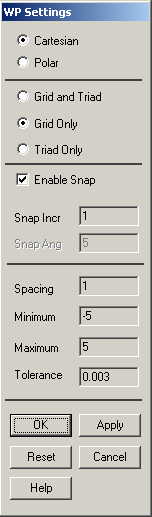
The following
window comes up |
|
Check the Cartesian
and Grid Only buttons |
|
Enter the values
shown in the above. |
|
Go to the ANSYS
Main Menu |
|
Click
Preprocessor>Modeling>Create>Keypoints>On
Working Plane |
|
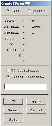
The following
window comes up |
|
Now we will pick
the end points of the trusses.
|
5 meters is now 1
X 5 units, since each cell in the grid is 1 unit across, 5 meters is
5 cells wide. |
|
Using this
conversion select the keypoints on the
workplane grid. Your points should look
like this. |
|
|
If you cannot see
the complete workplane then go to
Utility Menu>PlotCntrls>Pan Zoom Rotate
and zoom out to see the entire workplane.
|
|
Now create lines
connecting the keypoints
|
Click on
Preprocessor>Modeling>Create>Lines>Lines>Straight Line
|
|
Create lines by
picking keypoints to make the figure
shown below. |
|
MATERIAL PROPERTIES
|
Go to the ANSYS
Main Menu |
|
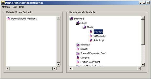
Click
Preprocessor>Material Props>Material Models. In the window that comes
up choose
Structural>Linear>Elastic>Isotropic.
The following window will appear. |
|
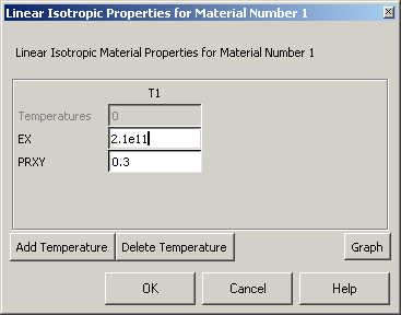
Double Click
Isotropic. The following window comes up. |
|
Fill in 2.1e11 for
the Young's modulus and 0.3 for Poisson's Ratio. Click OK |
|
Now the material 1
has the properties defined in the above table. We will use this
material for the structure. |
ELEMENT PROPERTIES:
SELECTING ELEMENT TYPE:
|
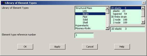
Click
Preprocessor>Element Type>Add/Edit/Delete...
In the 'Element Types' window that opens click on Add... The following
window opens. |
|
Type 1 in the
Element type reference number. |
|
Click on Structural
Beam and select 2D elastic. Click OK. Close the 'Element types'
window. |
|
So now we have
selected Element type 1 to be a structural Beam- 2D elastic element.
The trusses will be modeled as elements of type 1, i.e. structural
beam element. This finishes the selection of element type. |
|
Now we need to
define the cross sectional area, the second moment of inertia etc. for
this element. |
|
Go to
Preprocessor>Real Constants.
|
|
In the "Real
Constants" dialog box that comes up click on Add |
|
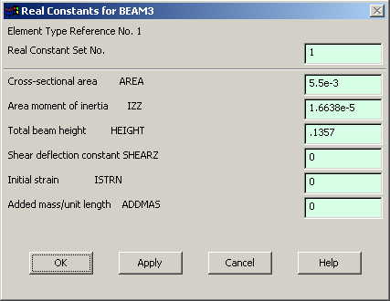
In the "Element
Type for Real Constants" that comes up click OK. The following window
comes up |
|
Type in 5.5e-3 for
cross sectional area, calculate Izz from
the value of the cross-sectional area and polar radius of gyration and
enter it. Also calculate and enter the height and click on OK. The
height of the beam is required to calculate the maximum stress, which
will be at the top surface of the beam. |
|
We have now defined
the geometric properties of the beam element. |
MESHING:
DIVIDING THE STRUCTURE INTO ELEMENTS:
|
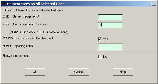
Go to
Preprocessor>Meshing>Size Controls>Manual Size>Lines>All Lines.
In the menu that comes up type 1 in the field for 'Number of element
divisions'. |
|
Click on OK.
|
|
Now
go to
Preprocessor>Meshing>Mesh>Lines |
|
Select all the
lines and click on OK in the "Mesh Lines" dialog box.
|
|
Now each line is a
truss element (Element 1). |
BOUNDARY CONDITIONS AND
CONSTRAINTS:
APPLYING BOUNDARY CONDITIONS
|
The tower is
constrained in the DOFs at the bottom
node. |
|
Go to Main Menu
|
|
Click on
Preprocessor>Loads>Define Loads>Apply>Structural>Displacement>On
Keypoints.
|
|
Select the
keypoint on which you want to apply
displacement constraints. The following window comes up. |

|
Select All DOF and
click OK. |
APPLYING FORCES
|
Go to Main Menu
|
|
Click on
Preprocessor>Loads>Define Loads>Apply>Forces/Moment>On Nodes.
|
|
Select the top
right node and the top left node. |
|
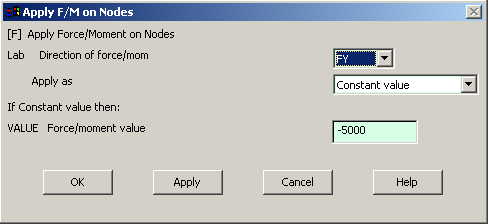
Click on OK in the
'Apply F/M on Nodes' window. The following window will appear.
|
|
Enter the value of
the force. |
The
figure looks like this now.
Now the
Modeling of the problem is done
SOLUTION:
Go to
ANSYS
Main
Menu>Solution>Analysis Type>New Analysis.
Select
static and click on OK.
Go to
Solution>Solve>Current LS
Wait
for ANSYS to solve the problem.
Click
on OK and close the 'Information' window
POST-PROCESSING:
Listing
the results
Go to
ANSYS Main Menu
Click
on
General
Postprocessing>List Results>Nodal Solution.
The following window will come up.
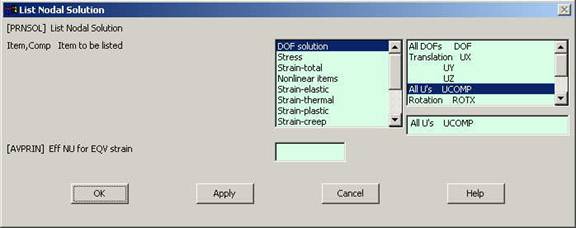
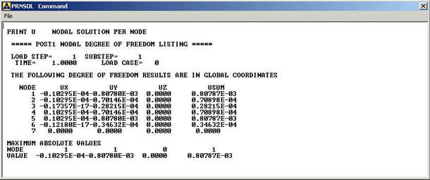
Select
DOF solution and All U's. Click on OK. The
nodal displacements will be listed as follows.
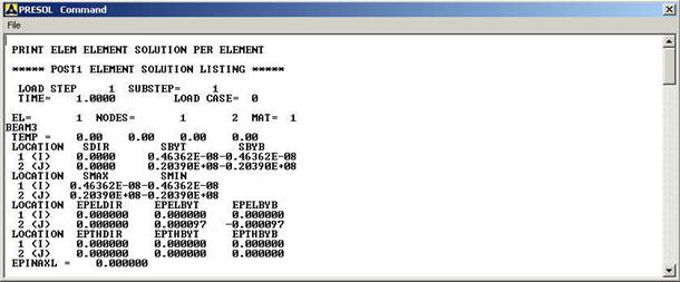
Similarly you can list the stresses for each element by clicking
Gen
Postprocessing>List Results>Element
Solution.
Now select LineElem Results. The following
table will be listed.
MODIFICATIONS:
You can
also plot the displacements and stress.
Go to
General
Postprocessing>Plot Results>Contour
Plot>Element Solution.
The following window will come up.
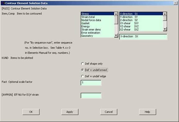
Select
a stress to be plotted and click OK. The output will be like this.