Structural #1: Analysis of a power transmission tower
Introduction:
In this
example you will learn to use the 2-D Truss element in ANSYS.
Physical Problem:
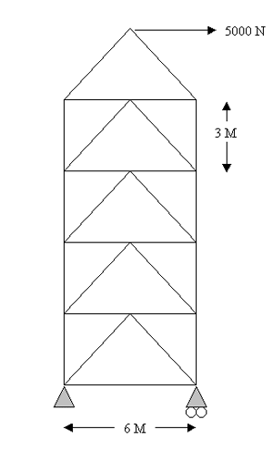
A power
transmission tower is a common example of a structure that is made up of
only truss members. These towers are actually 3-D structures, but for
the sake of simplicity we will take a cross-sectional face of the tower.
The tower is mainly subjected to loading in the vertical direction due
to the weight of the cables. Also it is subjected to forces due to wind.
In this example we will consider only loading due to the weight of the
cables, which is in the vertical direction.
Problem Description:
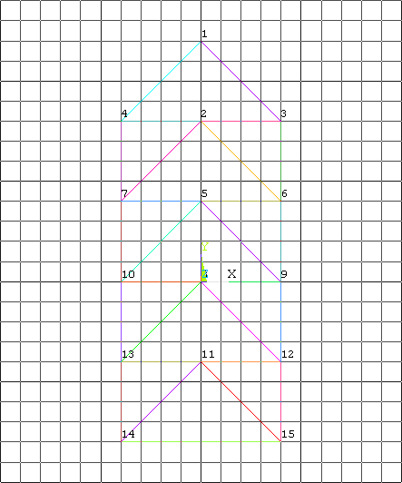
 |
The tower is made
up of trusses. You may recall that a truss is a structural element
that experiences loading only in the axial direction.
|
|
Units: Use S.I.
units ONLY |
|
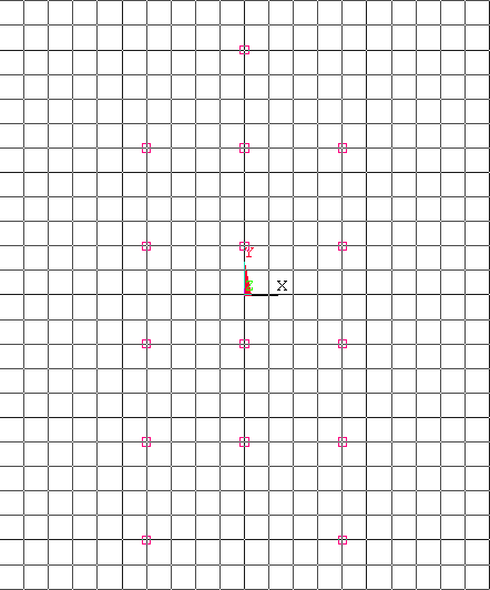
Geometry:
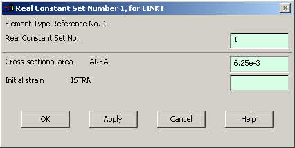
the cross sections of each of the truss members is
6.25e-3 sq. meter. |
|
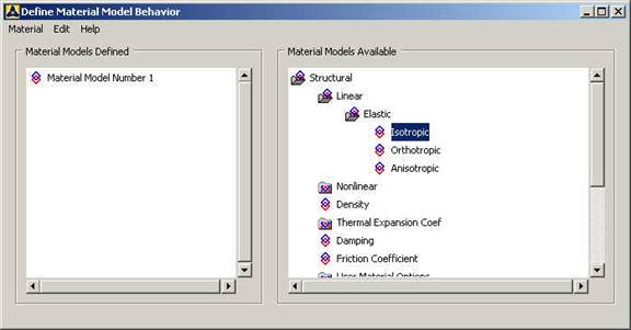
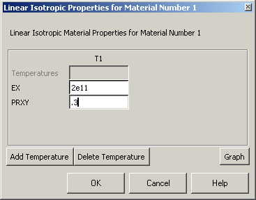
Material: Assume
the structure is made of steel with modulus of elasticity E=200
GPa.
|
|
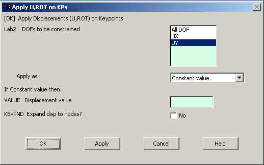
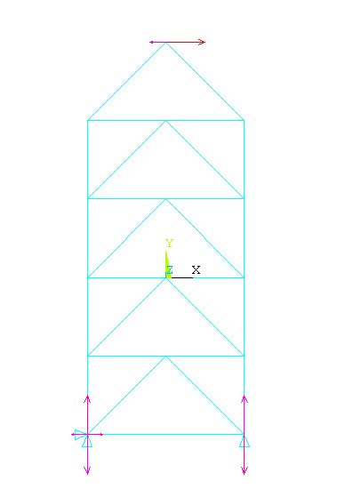
Boundary
conditions: The tower is constrained along X and Y directions at the
bottom left corner, and along Y direction at the bottom right corner.
|
|
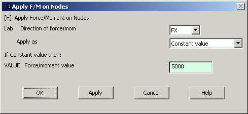
Loading: The tower
is loaded at the top. The load is in horizontal direction only, and
its magnitude is 5000 N. |
|
Objective:
 |
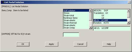
To determine
deflection at each joint. |
|
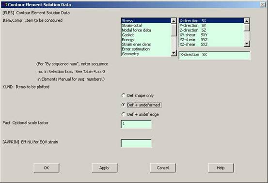
To determine
stress in each member. |
|
To determine
reaction forces at the base. |
|
|
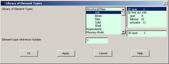
Type 1 in the
Element type reference number |
|
Click on Structural
Link and select 2D spar. Click OK. Close the 'Element types' window.
|
|
So now we have
selected Element type 1 to be a structural Link- 2D spar element. The
trusses will be modeled as elements of type 1, i.e. structural link
element. This finishes the selection of element type. |
|
Now we need to
define the cross sectional area for this element. |
|
Go to
Preprocessor>Real Constants |
|
In the "Real
Constants" dialog box that comes up click on Add |
|
In the "Element
Type for Real Constants" that comes up click OK. The following window
comes up. |