·
Check
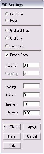
the Cartesian and Grid Only buttons
·
Enter
the values shown in the figure above.
In this problem we
will model the car, then model the wind tunnel around it, then subtract
the volume of the car from the wind tunnel. At this point we will then
apply fluid flow to the wind tunnel and see how its flow is impeded due
to the car.
·
Now, we
will create the model.
·
Click
Preprocessor>-Modeling->
and create the keypoints to define the car.
·
NOTE:
It makes the creation of the car MUCH easier to go to the ANSYS Main
Menu (the top bar) and select PlotCntrls>Pan
Zoom Rotate and select the Isometric view (ISO). This simply
allows you a better view of the 3 dimensional
keypoints forming the car.
·
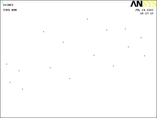
Once
the keypoints are finished, the model should
look like the figure below.
·
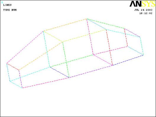
Now
that the keypoints have been created,
connect them with lines to form the body of the car.
·
If any
lines are created incorrectly, proceed to
Preprocessor>Modeling>Delete>Lines Only
to
delete the incorrect line without deleting the
keypoints forming it.
·
The car should now look like this:
·
Once
the lines have been created, create Arbitrary Areas defined by Lines to
form the outer shell of the car.
·
NOTE: DO NOT FORM THE 2 VERTICAL AREAS WITHIN THE CAR. This will only
make creating the volume of the car much more difficult.
·
Once
the areas defining the shape of the car are all created, define a volume
by areas. Since only the areas on the outside of the car have been
created you may choose “PICK ALL” to select all the areas that make up
the car and form them into a single volume.
·
If an
error appears it is most likely because either an area was not selected
(if you chose to do the selection by hand) OR an area was created within
the volume unintentionally. If this is the case, you need to go to
Preprocessor>Modeling>Delete>Areas Only
and delete the incorrect area.
·
Once
the car volume is finished, create the Block surrounding it that will
form the wind tunnel.
·
Now go
to
Preprocessor>Modeling>Operate>Booleans>Subtract>Volumes
and select the wind tunnel block, then the car and click OK.
This now deletes the car volume and leaves a hollow space within the
wind tunnel in the shape of the car. The reason for this step is that
the wind tunnel block will be defined as nothing but Air, so the volume
that was removed (in the shape of the car) acts as an impedance for air
(as it would in real life) and causes the deflection we desire to plot.
·
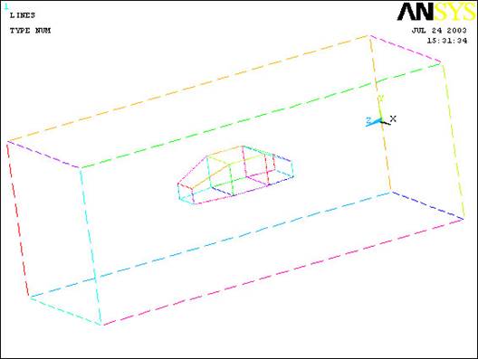
If you
have done everything correctly the model should look like this: (in an
isometric view)
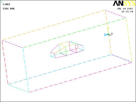
The modeling of the
problem is done.
ELEMENT PROPERTIES
SELECTING ELEMENT
TYPE:
·
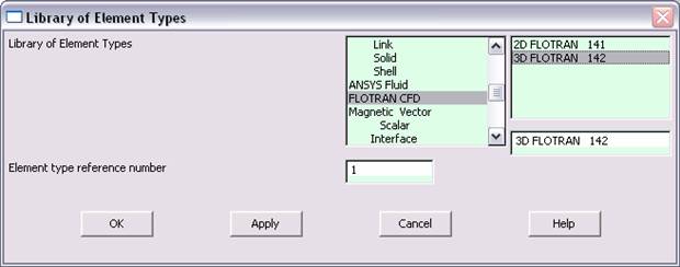
Click
Preprocessor>Element Type>Add/Edit/Delete...
In the 'Element Types' window that opens click on Add... The
following window opens:
·
Type
1 in the Element type reference number.
·
Click
on Flotran CFD and select
3D Flotran 142. Click OK. Close
the 'Element types' window.
·
So now
we have selected Element type 1 to be a Flotran
element. The component will now be modeled using the principles of fluid
dynamics. This finishes the selection of element type.
DEFINE THE FLUID
PROPERTIES:
·
Go
to
Preprocessor>Flotran Set Up>Fluid
Properties.
·
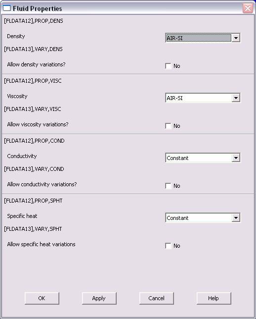
On the
box, shown below, make sure the first two input fields read AIR-SI,
and then click on OK. Another box will appear. Click OK
to accept the default values.
·
Now
we’re ready to define the Material Properties
MATERIAL PROPERTIES
·
Go to
the ANSYS Main Menu
·
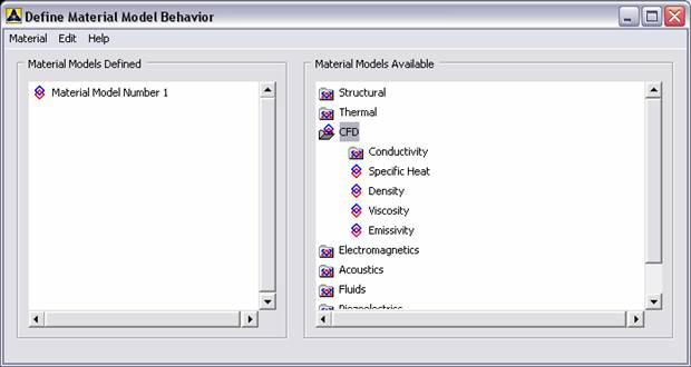
Click
Preprocessor>Material Props>Material Models.
The following window will appear
·
As
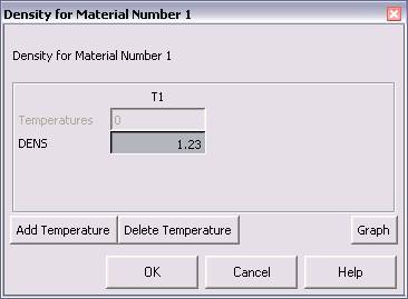
displayed, choose CFD>Density. The following window appears.
·
Fill in
1.23 to set the density of Air. Click OK.
·
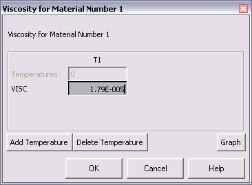
Now
choose CFD>Viscosity. The following window appears:
·
Fill in
1.79e-5 to set the viscosity of Air. Click OK
·
Now the
Material 1 has the properties defined in the above table so the Material
Models window may be closed.
MESHING:
DIVIDING THE CHANNEL
INTO ELEMENTS:
·
Go to
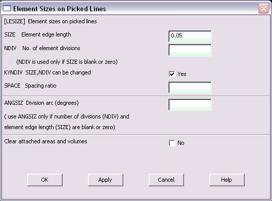
Preprocessor>Meshing>Size Cntrls>ManualSize>Lines>Picked
lines. Now
select all the lines that form the car and Click OK. (NOTE: It
will make selection much easier if you go to the ANSYS Main Menu (Top
Bar) and select Plot>Lines. This will allow you to view the
lines that form the volume.) In the window that comes up type
0.05 in the field for 'Element edge length'.
·
Click
on OK. Now return to
Preprocessor>Meshing>Size Cntrls>ManualSize>Lines>Picked
lines and
select the edges of the block forming the wind tunnel around the car.
·
Set the
‘element edge length’ to 0.5.
·
Now
when you mesh the figure ANSYS will automatically create a mesh, whose
elements have a edge length of 0.05 m
at the car, and slowly lengthen until they are approximately 0.5 m
at the edge of the wind tunnel. This is because the mesh should be
finer at the car because that’s where we want a more precise analysis.
·
Now go
to
Preprocessor>Meshing>Mesh>Areas>Free.
Click Pick All. The mesh will look like the following.
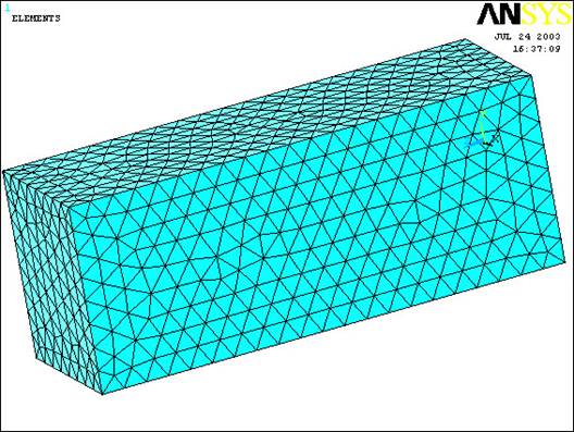
NOTE: The car is
meshed safely inside the block. Do not be alarmed that you can not see
it.
BOUNDARY CONDITIONS
AND CONSTRAINTS
·
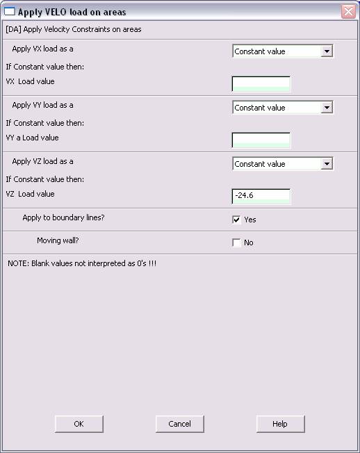
Go to
Preprocessor>Loads>Define Loads>Apply>Fluid CFD>Velocity>On Areas.
Pick the area of the wind tunnel block facing the front of the car and
Click OK. The following window comes up.
·
Enter
-24.6 in the VZ value field and click OK. The -24.6 corresponds
to the velocity of 24.6 meters per second of air flowing over the car.
·
Then,
set the Velocity to ZERO along all of the axial sides of the
block enclosing the car. This is because of the “No Slip Condition”
acting on the walls of the wind tunnel. (VX=VY=0 for all sides)
·
Go to
Main
Menu>Preprocessor>Loads>Define Loads>Apply>Fluid CFD>Pressure DOF>On
Areas.
Pick the area behind the car and click OK.
·
Enter
0 as the pressure value. (This sets the pressure as atmospheric
allowing the air to pass over the car)
·
Once
all the Boundary Conditions have been applied, we can move on to solving
the problem.
SOLUTION
·
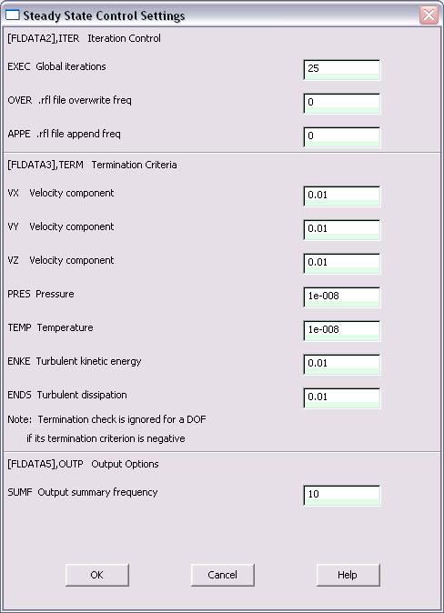
Go
to ANSYS
Main
Menu>Solution>Flotran Set Up>Execution Ctrl.
·
The following window appears. Change the first input field value to
25, as shown. No other changes are needed. Click OK.
·
Go
to
Solution>Run FLOTRAN.
·
Wait for ANSYS to solve the problem.
·
Click on OK and close the 'Information' window.
POST-PROCESSING
·
Plotting the velocity distribution…
·
Go
to
General
Postproc>Read
Results>Last Set.
·
Then go to
General
Postproc>Plot
Results>Contour Plot>Nodal Solution.
The following window appears:

·
Select DOF Solution and Velocity VSUM and Click OK.
·
This is what the solution should look like:

Despite what you may think this is the correct solution. Now, in order
to view the effects of the air flow on the car within the wind tunnel we
must move the working plane so that it’s positioned along the longest
axis of the car and tell ANSYS to show a cut away view. This is how you
accomplish that: