
1. Modeling With Pro/Engineer
Wlidfire
TO Get Started
1. To start the program, click on the "proewildfire" icon on the desktop
if you are using mechanical engineering computer cluster. Alternatively, you
can go to Start on the taskbar and select run. Then type "proe".
2.
You can also set the working directory to whichever directory you want your
files to be saved in. In order to do so, go to File --> Set Working Directory.
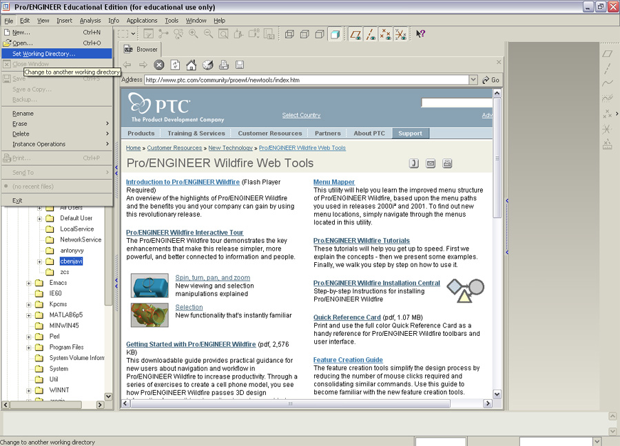
And then select your preferred working directory.
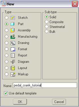
3. Select File --> New (or Ctrl + N, or click on the icon  )
)
You should see the following window. Type in the filename, click on "part"
and "solid" as shown below.
Modeling
First of all, we need to know few things about Pro/Engineer.
1. One can extrude the 2D sketch into a 3D model by using the "Extrude
Tool"  .
.
2. Before selecting ,
one should specify the plane the model will be extruded.
3. The model is not complete until you select
4. Pro/Engineer allows you to roughly sketch the model and then modify the dimensions
of the model later on. One should modify the smallest dimension first before
continuing to the larger dimensions.
5. One should be very careful when specifying the dimensions. Also please note
that the dimensions have to be specified with respect to the plane.
6. By typing Ctrl + R, the model is repainted.
7. If you want the sketch to fit to the screen, go to View --> Orientation
--> Refit
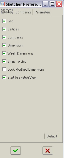
7. You should set the sketcher preference by go to Sketch --> Options. Then
the following window should show up. Click on Grid, and Snap To Grid.
Now, we can start sketching the model.
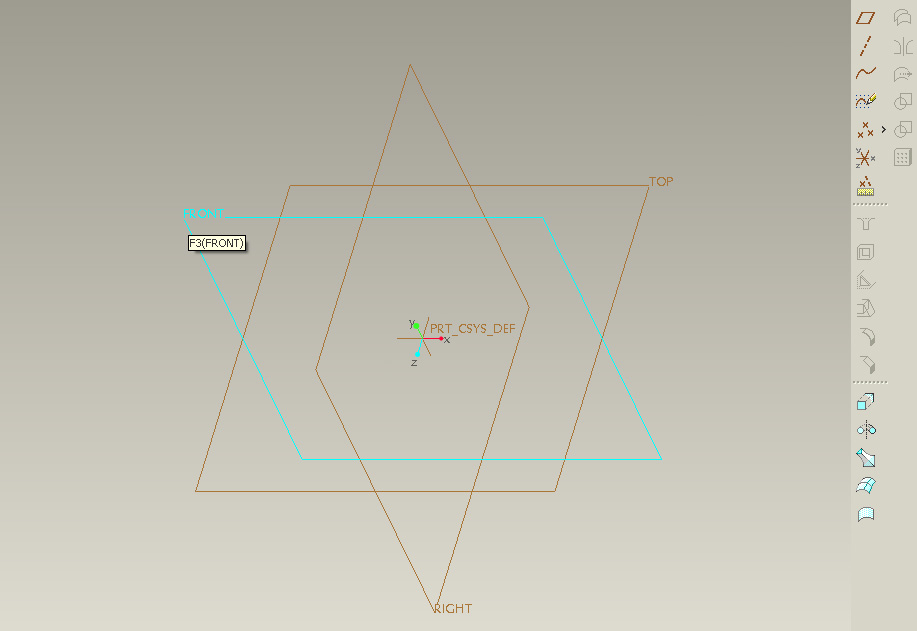
1. First click on the "Front" plane, because we want to extrude the
2D model along the front side of the pedal crank. While moving the mouse, you
could see each plane will become highlighted in blue. Click on it once, then
you will see that the "Front' plane is not highlighted in red.
Then
click on
which is on the lower right hand corner of the screen.
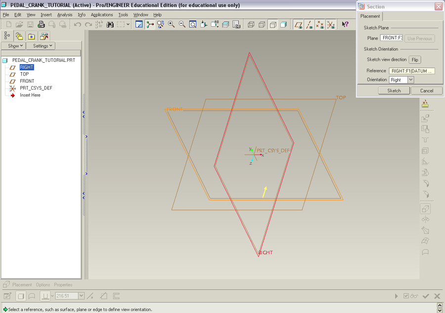
2. Automatically
the plane perpendicular to the "Front" plane and the "Front"
plane are highlighted. Click Sketch on the Section window.
Modify the extrusion depth from the bottom dashboard. (extrusion depth = 0.4375in)
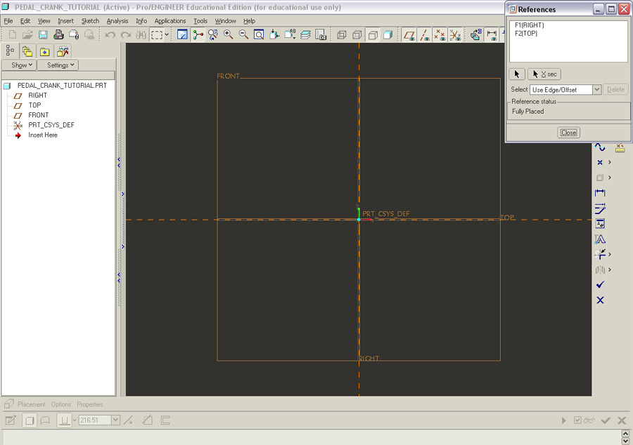
You should now see the following. Click Close on the Reference
window.
3. Create An Arc
Now you can see the toolbar on the right hand side of the screen.
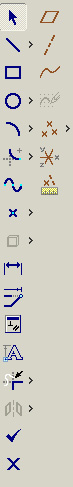
Click on the 5th icon  (create arc by center and endpoints: the first and second points specify the
arc's endpoints. The third point is the center point of an arc. )
(create arc by center and endpoints: the first and second points specify the
arc's endpoints. The third point is the center point of an arc. )
Click on 3 points to make an arc on the left side and repeat to create another
arc. (Note: You need to click on the
icon again; otherwise the software will create an arc of the same radius) You
should see the following.
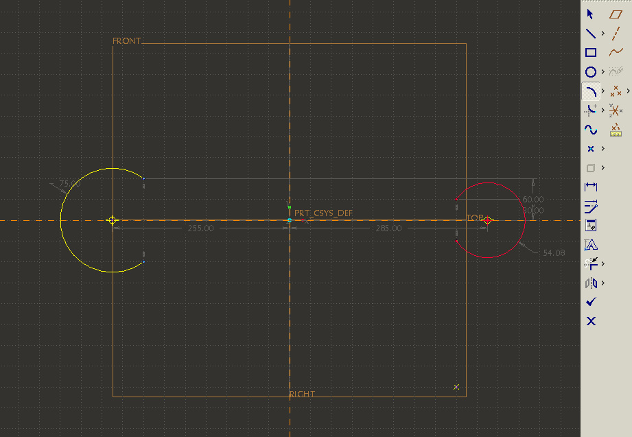
Then create the line connecting two arcs. Click on  .
Then select two endpoints for each line with left mouse button and click the
middle mouse button to confirm creating the line. Do not worry about the dimensions
for now. The next step will show you how to modify those dimensions.
.
Then select two endpoints for each line with left mouse button and click the
middle mouse button to confirm creating the line. Do not worry about the dimensions
for now. The next step will show you how to modify those dimensions.
Modifying Dimensions
The dimensions specified in light grey are weak dimensions, meaning that they
could be overridden by the user. In order to override those dimensions, simply
click on the icon  ,
and then double click on the weak dimension you want to edit. Please note that
the dimensions used here are in cm.
,
and then double click on the weak dimension you want to edit. Please note that
the dimensions used here are in cm.
(Note that you can click on  to move points around to change the sketch)
Here is the sketch after modified dimensions. Note that you can zoom in and
out by clicking on 
(Note that the order of which dimensions to be changed first matters. You should
not change the radius of the arc first.)
Here is the finished sketch with correct dimensions.
Select Done from the main menu. Main Menu --> Sketch --> Done or click
on  .
.
Then click on the check mark (the green check mark), you should see the following
window.
4. Create a Hole
Now click on  which will help us create hole in the part. Key in 1.905 for the hole's diameter
and select the "Through All" icon
which will help us create hole in the part. Key in 1.905 for the hole's diameter
and select the "Through All" icon

If you want a better view of the model, type Ctrl + D (or go to View -->
Orientation --> Standard Orientation). You should be able to see
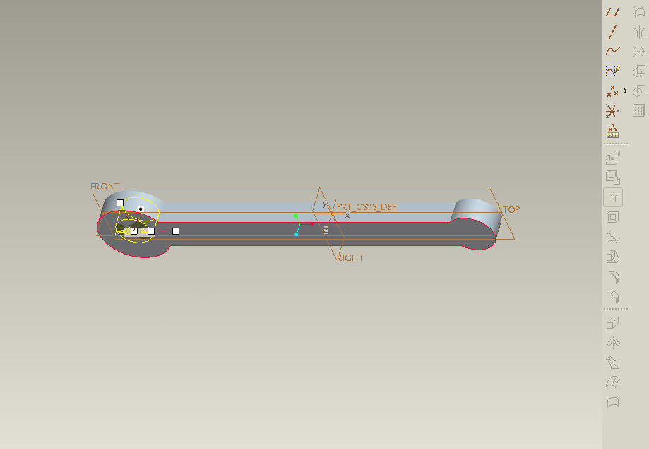
Now the program needs to know where to locate the hole. You can see the 4 white
boxes. Those are reference frame of the hole. You would have to drag the box
that is not in the center of the cylinder (the top box and the far right box)
to one of the plane you wish to refer the hole's location to. For example, you
can drag the far right box to the "RIGHT" plane and drag the other
white box to the "TOP" plane. You can tell when the box is dragged
to the desired plane, since the plane will be highlighted in blue.
Then by double clicking on the yellow number, you can modify the location of
the hole.
Repeat the process for the other hole (diameter = 1.27cm). Your model should
look like the one below.
Save your file.
Here is the pedal crank model
using Pro/Engineer. Right click on the link and select "Save
Target As...". Make sure that the file is saved with the ".prt" lastname.
Determine
the total volume of pedal crank
You
have now created the pedal crank design identical to the one used in problem
4. The following steps will allow you to change some features of
the "standard" pedal crank design.
1) Adding
Fillet Radius
2) Edge
Rounding
3) Changing
the Geometry of the Middle Portion of the Pedal Crank
4)
Creating
and Extruding Cross Section of the Middle Portion of Pedal Crank
You need to import the file to the type that ANSYS can read. One of those
files is "IGES" file.
In order to import the .prt file to .igs file, go to
FILE ->
Save a Copy
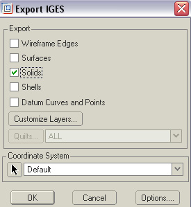
Then select the type of file from drop down menu in "Save a Copy"
window.
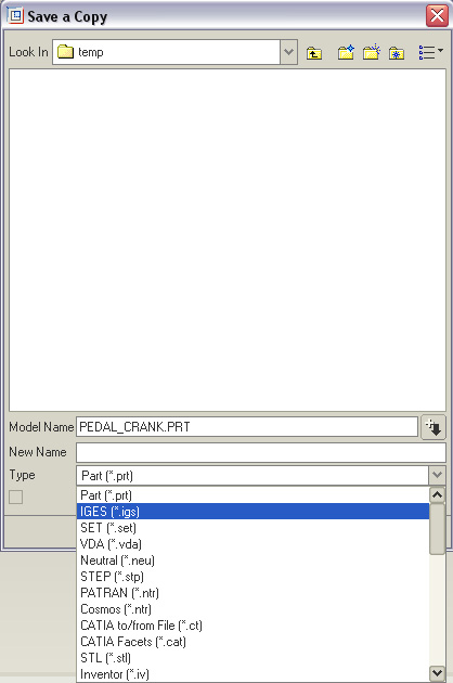
You could
also save it as a CATIA file which is also readable in ANSYS. Select Solids.
Then click OK.
The next step will be to import this CAD file into ANSYS, set up material properties,
apply loads and solve for stress and strain occurred on the model.
GO
TO STEP 2
=