|
Carnegie
Mellon University Mechanical Engineering |
Problem 3 : Plate with a Hole
|
Carnegie
Mellon University Mechanical Engineering |
Problem
Description
# Material : The plate is made of steel with Modulus of elasticity E = 200 GPa,
and Poisson's ratio = 0.25
# Unit : SI Units ONLY. It is important to convert pressure to "Pa"
and all dimensions to "meters".
# Boundary Conditions : We will use symmetry conditions to solve this problem,
by considering only the top right quarter of the plate. Therefore, the boundary
conditions for the plate are symmetry conditions on the left and bottom parts
of the plate.
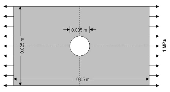
# Loading : Uniform tensile Load with magnitude 1 MPa acting on both left and
right sides of the plate (Since we're using symmetry, we will apply pressure
to only the right side of the top right quarter of the plate) Because we are
performing a linear analysis, a uniform load/area of 1 MPa is appropriate. Stresses,
strains and displacements for any other magnitude of loading can be determined
by simply re-scaling the results from this model.(eg. To obtain results for
a 100MPa load, simply multiply results from this model by 100)
# Objectives :
1. To use symmetry conditions to determine
magnitudes of maximum stress, minimum stress and their locations on the plate
after the load is applied.
# Things to hand in :
2. To model the plate using a default mesh (coarse mesh) and using mesh size
control to increase element resolution (fine mesh). You will then determine
how element resolution affects the maximum and minimum stresses.
1.
Contour plot
# Figure and Dimensions:
2. Query of maximum stress
3. Query of minimum stress
4. Plot of stress xx and stress yy VS y along y=0
1.
Specify Geometry
There are several ways to create the model geometry in ANSYS. For this problem,
we will use two ways to create the specified object. The first method is to
define keypoints then create area rectangles through these keypoints. The second
method is to define key points and create lines. After we have the boarder of
the object, we will then create an area.
However, in order to see their numbers when creating keypoints, we will need
to turn on the keypoint numbers.
ANSYS UTILITY MENU -> PlotCtrls -> Numbering...
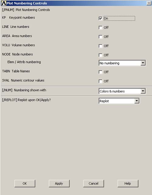
check the box next to "Keypoint numbers" to turn it on.
Then click OK to close the dialog box.
First Method
Second Method
The First Method: Merging Areas
1.1 CREATE KEYPOINTS
In this step, we will create 6 keypoints needed to create the plate areas.
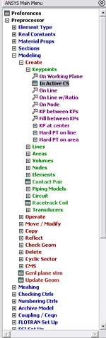
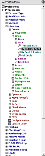
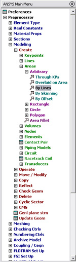
PREPROCESSOR -> -Modeling - Create
CREATE -> -Keypoints
KEYPOINTS
-> In Active CS...
The input box "Create Keypoints in Active Coordinate System" should
appear on the screen as shown in figure below.
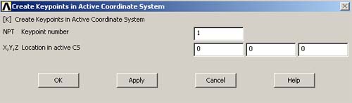
Then create 6 keypoints at 6 different locations by enter the Keypoint numbers
and locations as following:
Keypoint number 1 : (0, 0, 0) -> Click Apply
Keypoint number 2 : (0.0125, 0, 0) -> Click Apply
Keypoint number 3 : (0.025, 0, 0) -> Click Apply
Keypoint number 4 : (0.025, 0.0125, 0) -> Click Apply
Keypoint number 5 : (0.0125, 0.0125, 0) -> Click Apply
Keypoint number 6 : (0, 0.0125, 0) -> Click OK
Note: Don't worry if you enter wrong numbers. You can always reassign the coordinate
by overwriting the old values for X, Y and Z on any keypoints with the new values.
ANSYS will take the latest values you input.
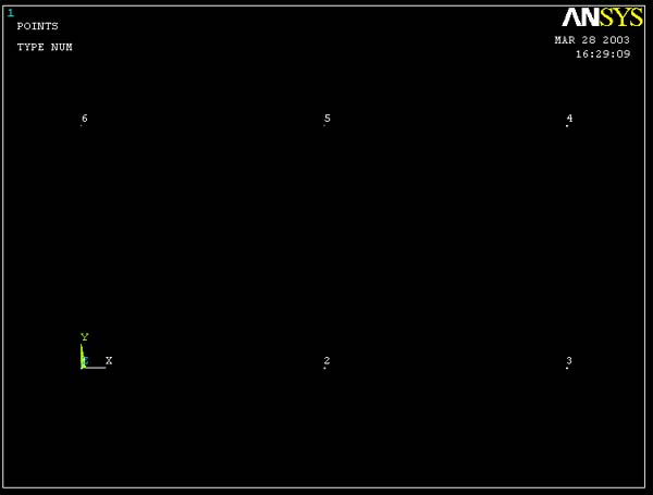
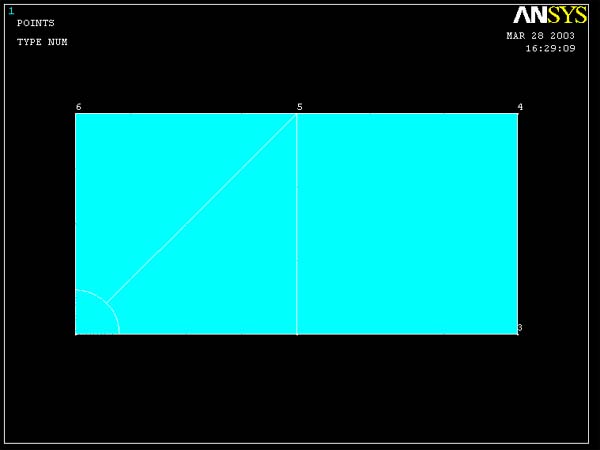
You should now see 6 keypoints on the ANSYS Graphics window as shown in the
figure below.
1.2 CREATE AREA THROUGH KEYPOINTS
The next step, we will create three areas through the keypoints we have created.
These three areas are arranged to allow improvements in element resolution which
will also improve the accuracy of the analysis.
PREPROCESSOR -> -Modeling - Create
CREATE -> -Area -Arbitrary
ARBITRARY
-> Through KPs
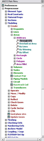
The Create Area Thru KPs window pops up. Pick Keypoints to create areas
as followings:
1. Pick Keypoint numbers 1, 5, 6 (Pick in that order).
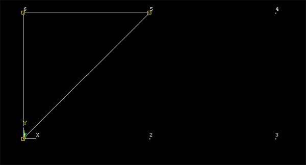
Then click
OK.
2. Pick Keypoint numbers 1, 5, 2.
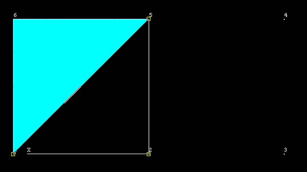
Click OK.
3. Pick Keypoint numbers 2, 3, 4, 5.
Click OK.
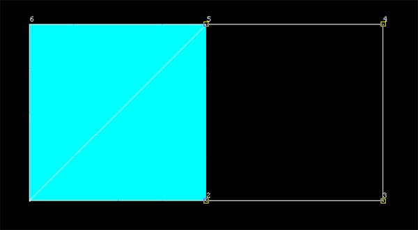
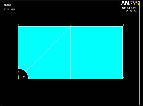
Then you would have the connected area of a rectangle with three different areas
in it.
1.3 CREATE CIRCULAR AREA (HOLE)
PREPROCESSOR -> -Modeling - Create
CREATE -> -Area -Circle
CIRCLE
-> Partial Annulus
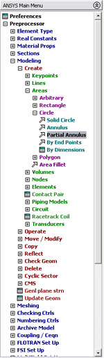
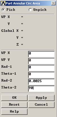
The PartAnnular Circ Area window should now appear on the screen. Fill in the
fields as shown in the figure.
 |
||
| Note : | ||
| WP X | = Circle center X-Coordinate | |
| WP Y | = Circle center Y-Coordinate | |
| Rad-1 | = Inner radii of the circle or cylinder. A value of zero or blank, or the same value for both Rad-1 and Rad-2, defines a solid circle or cylinder. | |
| Theta-1 | = Starting angles of the circle or faces of the cylinder. | |
| Rad-2 | = Outer radii of the circle or cylinder. | |
| Theta-2 | = Ending angles of the circle or faces of the cylinder. | |
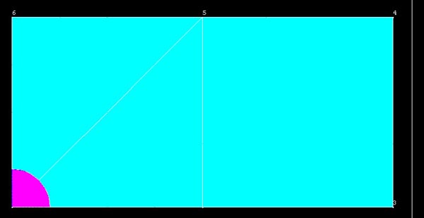
Click OK.
There should
be a circular area appears on your plate as shown :
1.4 SUBTRACT THE HOLE FROM PLATE
PREPROCESSOR -> -Modeling - Operate
OPERATE -> -Booleans -Subtract
SUBTRACT
-> Areas
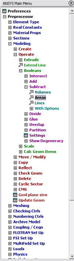
Pick the base areas from which you want to subtract first (The two triangular areas)
First, click
on one triangle. Do not click OK yet.
Then click on another triangle.
Now click
OK. ANSYS will know that the two area is the base area where
the next input area will be subtracted from.
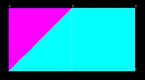
Now
pick the area to be subtracted (Circular area)
Click OK.
You should now have a plate with a hole as shown :
1.5 MERGE GEOMETRY
To connect all parts together, we will have to merge the keypoints.
PREPROCESSOR -> Numbering Controls
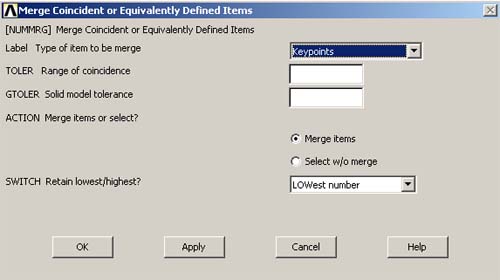
NUMBERING CONTROLS -> Merge Items...
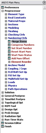
Choose Keypoints in the label pick list. Then click OK to merge keypoints and
close the dialog box.
Second Method: Creating Area through Key Points
1.1 Create Key Points
PREPROCESSOR
-> -Modeling - Create
CREATE -> -Keypoints
KEYPOINTS
-> In Active CS...
Then, pick the following 8 points:
Keypoint number 1
: (0, 0, 0) -> Click Apply
Keypoint number 2 : (0.0025,0,0) ->Clicl Apply
Keypoint number 3(0.0125, 0, 0) -> Click Apply
Keypoint number 4 : (0.025, 0, 0) -> Click Apply
Keypoint number 5 : (0.025, 0.0125, 0) -> Click Apply
Keypoint number 6 : (0.0125, 0.0125, 0) -> Click Apply
Keypoint number 7 : (0, 0.0125, 0) -> Click Apply
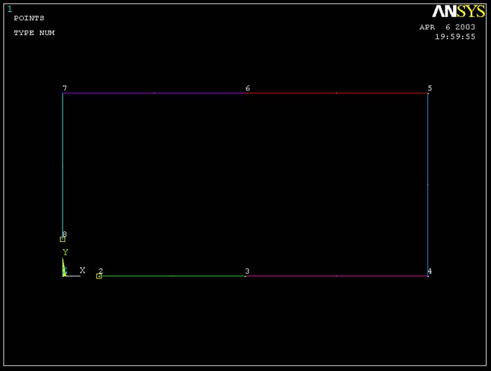
Keypoint number 8 : (0, 0.0025, 0) -> Click OK
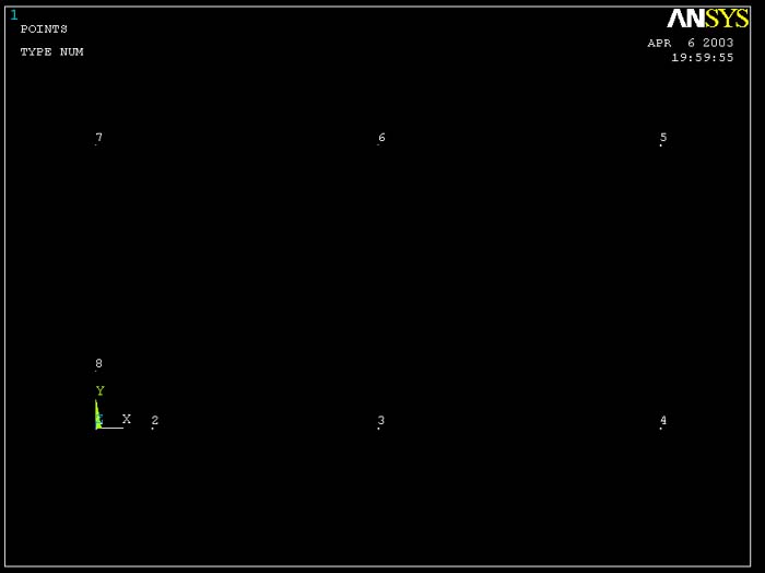
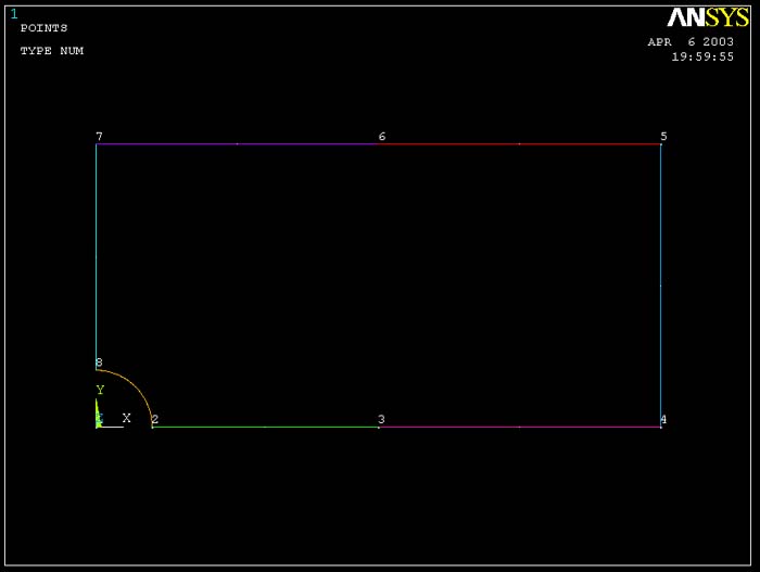
Then, you will see the figure below which indicates every kep points created with its label.
1.2 Create Lines--Straight Lines and Arc.
Here, we have to create straight lines as well as an arc so that we get the same area as from the previous method.
PREPROCESSOR -> Modeling
MODELING -> Lines
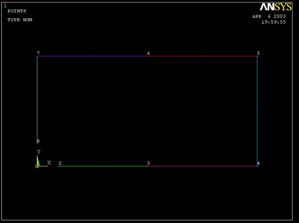
LINES -> Straight Lines
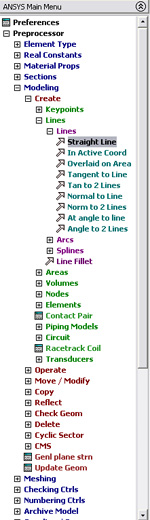
Then, select every line that composes the circumference of the specified object.
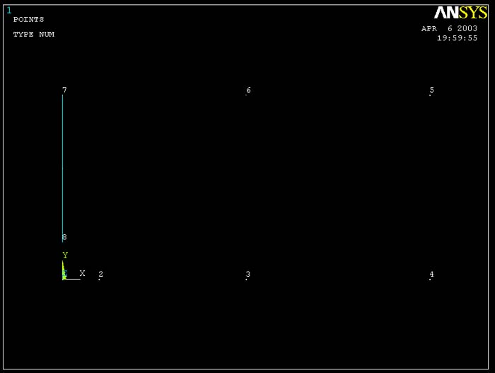
And so on,
Now, we will have to create an arc.
PREPROCESSOR -> Modeling
MODELING -> Arcs
ARCS -> By End KPs & Radius
The window will prompt you to pick points which are the end points of your arc. So pick point 2 and 8.
Then click OK. You will see the same window again. Now, you have to enter any point which is inside the circle. In this case, you just pick point 1.
You will then see the following window.
Enter 0.0025 for radius.
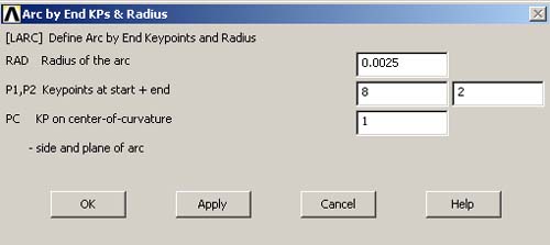
Click OK. Then you will get the connected lines needed to define an area.
We will move on to creating an area through lines.
1.3 Create Area
PREPROCESSOR -> Modeling
MODELING -> Areas
AREAS -> Arbitrary
ARBITRARY -> By Lines
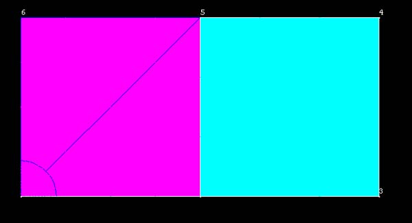
Pick all lines by clicking on each of them. Remember that you can unpick the line. But we will not need to do that since we have to select every line. After you selected a line, that line will be highlighted.
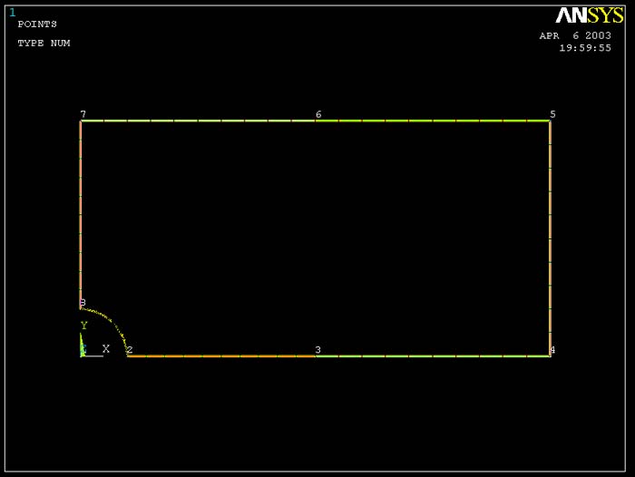
Click OK. Then, you will see the figure below.
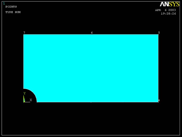
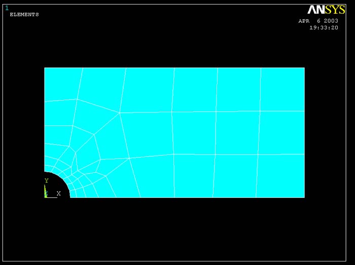
Now, we have defined an area that has the same shape as from the first method. However, when you mesh the area using Free command, the result will be different because ANSYS freely meshed the area which we have defined as the connected piece. If we look at the area created by the fisrt method, we will see that there were separated areas which will help the software determines the boundary where the meshes start and end. After you mesh the area created by the second method, you should get the following result.