| Turn off power supply. | |
| Remove the Co-ax/pigtail cable which connects the multimeter to the amplifier. |
| Disconnect the Co-ax cable from the fcn. gen., and replace it with a Co-ax "T" connector. Re-attach the Co-ax cable to one side of the "T" connector. | |
| Connect the other side of the "T" connector to input 1 of the oscilloscope with a Co-ax cable. | |
| Connect a Co-ax/pigtail cable to input 2 of the oscilloscope. |

| Attach an alligator clip to the GND terminal on the amplifier. | |
| Attach the other end of the alligator clip to the black leads from the motor and tach. | |
| Attach the red lead from the motor to the OUT terminal of the amplifier. | |
|
Clip the black lead from input 2 on the oscilloscope
to the ground alligator clip near the motor. Clip the corresponding
red lead to the red wire coming from the tach. | |
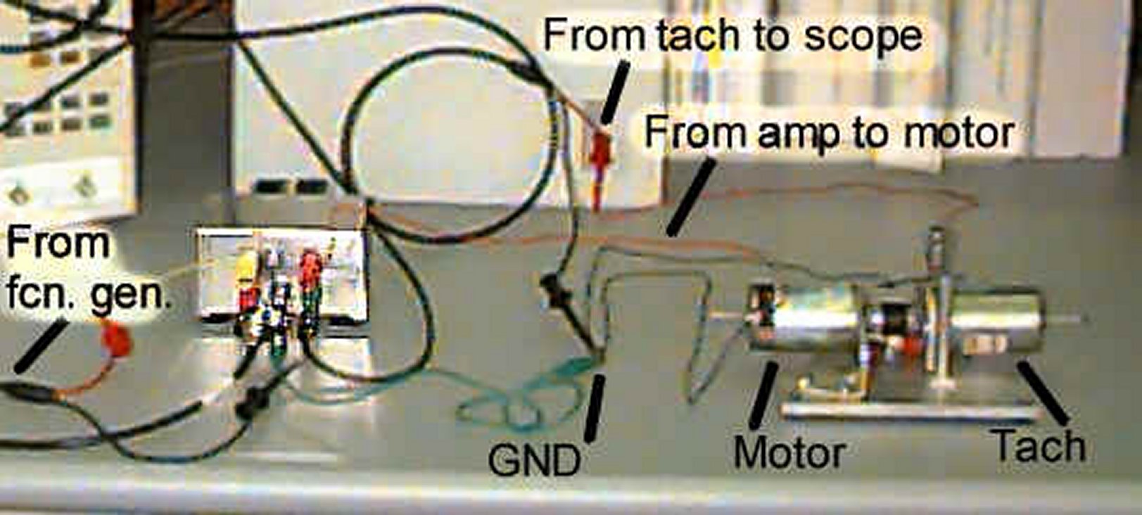
The entire setup is shown below: |

| Select a square wave with amplitude 100mV and frequency 1Hz. | |||||||||||||||
| Set the offset to 80mV. (This is really a 160mV offset). This offset is to ensure that the motor is always moving. If the motor is allowed to stop, static friction will affect the response. The step response will occur between a low speed and a high speed, rather than from a stop. | |||||||||||||||
| Setup oscilloscope. Note: Do NOT use autoscale. It won't pick up low frequency signals well.
| |||||||||||||||
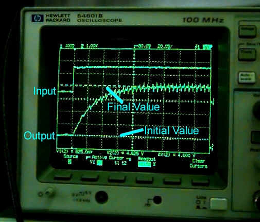
| Turn on power. The motor should spin, and you should get a response similar to that shown below. | |||||||||||||||
| Use the cursors to measure the difference in voltage levels between the initial and final values of the step response. Record this value. | |||||||||||||||
|
Print the resulting screen. |