CAE Project Assignment
Part 2: ANSYS Instructions
Outline
Based heavily on the ANSYS outline by Michael Paisner
Introduction
Part 2 of the CAE project is to do a Finite Element Analysis of your
wrench using Ansys. You must have completed Part 1 of the CAE project and
exported the wrench before you can begin on this second part of the project!
[Return to Outline]
ANSYS Instruction
Conventions
The following conventions are used in the Ansys Instructions:
| CAPITALS |
Menu Headings |
| Bold |
Menu Choices |
| Italics |
Enter text or a carriage return |
| Underlined |
Mouse button to be clicked in the ANSYS GRAPHICS window |
Examples:
UTILITY MENU -> File
ANSYS INPUT -> aplot <CR>
means go to the ANSYS INPUT window, enter the text aplot followed
by a carriage return.
When entering text, you must move the cursor over the window where the
text is to be entered.
[Return to Outline]
I. Start ANSYS
You must have completed Part 1 of the CAE project and exported the wrench
before you can begin on this second part of the project!
Using the same computer account which was used to draw the wrench, log
in at any of the HP computers in the Mechanical Engineering cluster (except
for hpme12) and open up ANSYS by going to the Xterm window and typing:
/data/ansys52/bin/xansys52 <CR>.
The XANSYS52 menu window will appear. Pick a location for this menu
by clicking once with the left mouse button. Choose:
XANSYS52 -> Interactive
INTERACTIVE ->
"Memory requested (megabytes)"
INTERACTIVE -> Run
The ANSYS_5.2_OUTPUT window will appear. Type a <CR> when
you are prompted to in this window. The ANSYS program will now begin.
Note: The UTILITY MENU is located at the top of the screen. The MAIN
MENU is located on the left side of the screen. Text should be entered
in the ANSYS INPUT window at the top left corner of the screen unless noted
otherwise.
[Return to Outline]
II. Import the Part
UTILITY MENU -> File
FILE -> Import
IMPORT IGES FILE -> highlight {your-iges-file}.igs
IMPORT IGES FILE -> OK
VERIFY ->Yes
Wait while the program transfers the file to the Ansys database. The
part will be transferred as surface acreas.
ANSYS INPUT -> aplot <CR>
- This will display the surface areas as a wireframe as shown in Figure
1.
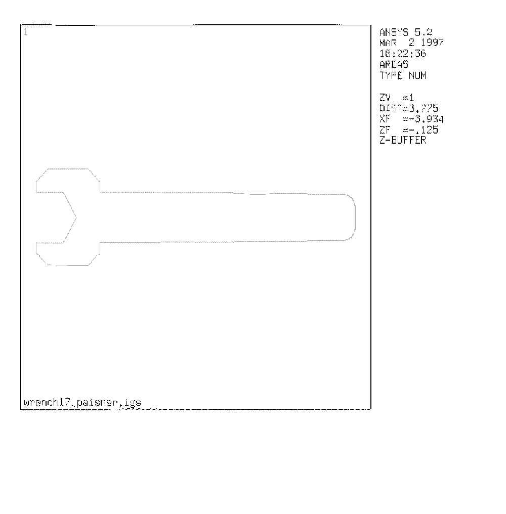
Figure 1
ANSYS INPUT -> /prep7 <CR>
ANSYS INPUT -> et,1,82 <CR>
This defines element type 82 and assigns it to reference 1.
Element type 82 is the plane stress quadratic displacement 8-noded
element.
[Return to Outline]
III. Mesh the Part
Meshing the part means it breaks the part into smaller pieces so that
the program can analyze the stresses within the part. Breaking the part
into many, small pieces (a fine mesh) will give more accurate results,
but will use up more time and memory. Using fewer, larger pieces (a rough
mesh) will run more quickly and use less memory, but will give less accurate
results.
MAIN MENU -> Preprocessor
PREPROCESSOR -> Material Props
MATERIAL PROPS -> Isotropic
ISOTROPIC MATERIAL PROPERTIES -> OK
ISOTROPIC MATERIAL PROPERTIES -> In the box for "Young's Modulus",
type 10e6.
ISOTROPIC MATERIAL PROPERTIES -> OK
PREPROCESSOR -> Mesh
MESH -> Areas
MESH AREAS -> Pick All. The part will turn light blue.
MESH AREAS -> OK
Wait for the program to mesh the part - this may take several seconds.
You may get warnings at this point. If you get warnings, click OK to
them. The part will now appear broken down into smaller pieces similar
to Figure 3.
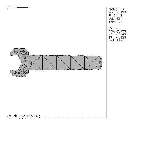
Figure 3
[Return to Outline]
IV. Apply Boundary
Conditions
This section tells the program what boundary conditions exist for the
movement of the wrench.
PREPROCESSOR -> Loads
ANSYS GRAPHICS WINDOW-> With the left mouse button,
select two nodes in the wrench jaws where the jaws will contact the
part to be twisted. Figure 4 shows the nodes.
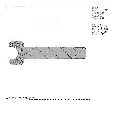
Figure 4
APPLY U,ROT ON NODE ->OK
APPLY U,ROT ON NODES -> "DOFs to be constrained" highlight
All DOF
APPLY U,ROT ON NODES -> "Displacement Value" type 0
APPLY U,ROT ON NODES -> OK
The figure should now look like Figure 5 with arrows marking the
points which are limited to zero displacement.

Figure 5
[Return to Outline]
V. Apply Loads
This section tells the program what loads are being applied to the part.

Figure 6
APPLY F/M ON NODES -> For "Direction of Force/Moment" choose
FY
APPLY F/M ON NODES -> For "Force/Moment value" enter the
load in pounds. If you chose the contact nodes such that the handle load
must point down, then enter a negative load.
APPLY F/M ON NODES -> OK.
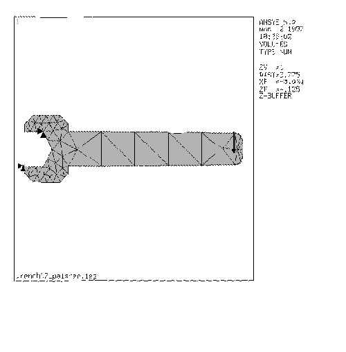
Figure 7
[Return to Outline]
VI. Print Image
UTILITY MENU -> PlotCtrls
PLOTCTRLS -> Capture Image
Click once with the left mouse button to set the window.
FILE -> Print
IMAGE HARD COPY -> Click next to the Print to: option to turn
it on.
IMAGE HARD COPY -> OK
FILE -> Close To close the capture image window.
[Return to Outline]
VII. Solve
ANSYS INPUT -> /solu <CR>
ANSYS INPUT -> solve <CR>
Wait while the program solves the problem. After the program reaches
a solution:
INFORMATION: SOLUTION IS DONE! -> Close
MAIN MENU -> General Postproc
GENERAL POSTPROC -> Plot Results
PLOT RESULTS -> Nodal Solu …
Directions are shown here to get contour plot of sigma xx. It should
be obvious how to get a contour plot of some other relevant stress
component.
CONTOUR NODAL SOLUTION DATA -> Highlight Stress
CONTOUR NODAL SOLUTION DATA -> Highlight X-direction SX
CONTOUR NODAL SOLUTION DATA -> OK
This displays the results data as contoured stress lines across the
model. You should now have a color representation of the stress of your
part similar to Figure 8.
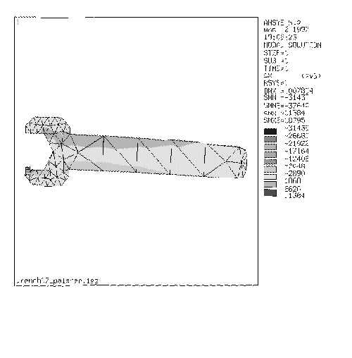
Figure 8
[Return to Outline]
VIII. Print Image
UTILITY MENU -> PlotCtrls
PLOTCTRLS -> Capture Image
Click once with the left mouse button to set the window.
FILE -> Print
IMAGE HARD COPY -> Click next to the Print to: option to turn
it on.
IMAGE HARD COPY -> OK
FILE -> Close To close the capture image window.
[Return to Outline]
IX.
Graph Stresses for a Cross Section of the Wrench
MAIN MENU -> General Postproc
GENERAL POSTPROC -> Path Operations
PATH OPERATIONS -> Define Path

Figure 9
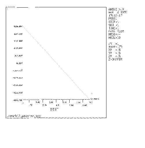
Figure 10
[Return to Outline]
X. Print Image
UTILITY MENU -> PlotCtrls
PLOTCTRLS -> Capture Image
Click once with the left mouse button to set the window.
FILE -> Print
IMAGE HARD COPY -> Click next to the Print to: option to turn
it on.
IMAGE HARD COPY -> OK
FILE -> Close To close the capture image window.[
Return to Outline]
XI. Exit the Program
UTILITY MENU -> File
[Return to Outline]