3. Machining with Pro/Manufacturing
First of all, download the following files: Pro/M.zip, which contains basic machining files and the blank from which your pedal crank will be cut defined.
![]()
3. Machining with Pro/Manufacturing
![]()
First of all, download the following files: Pro/M.zip,
which contains basic machining files and the blank from which your pedal crank
will be cut defined.
Start up Pro/Engineer Wildfire then upload the pre-made manufacturing files named prt0002.prt. Open the pre-made manufacturing filenamed crank_cnc.mfg. Make sure that our 'Pro/M' folder contains the crank_cnc.asm file. This file is made so that it contains CNC machine setup. Other files in the folder are tool's files, milling files, etc. Later on, you will need to select which tool part you want to use for roughcuts or finishcuts. There are two toolpart files. The toolpart is for roughcuts whose drill is of larger radius. And the other toolpart has smaller radius for finishcuts.
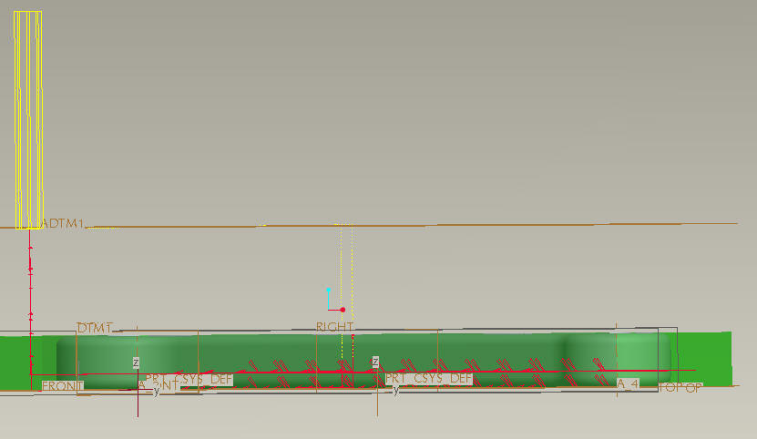
After you have loaded your workpiece. There
will be a Menu Manager on the upper right hand corner. Now to load your workpiece
into the model, select
Mfg Model --> Assemble --> Ref Model
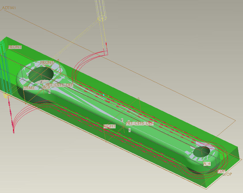
It will prompt you to open the .prt file which contains your pedal crank design. However, in the Pro/M.zip file,I included the prt0002.prt. The result should look like this in the main window. Now you have imported the part file which would need to match with the workpiece.
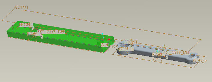
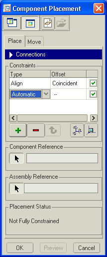
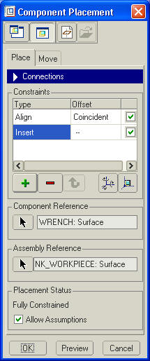
In order to match up the part file with the blank, we must constrain our model to be inside the workpiece. In 'Component Placement' window, we can specify the contraints that matches the surface of pedal crank with the corresponding surface. We will do this by making the fixturing holes in the model and the workpiece concentric, and the top faces of both coincident. The sidebar will have popped up to look like the following.
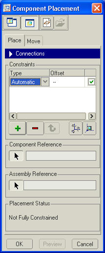
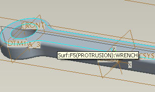
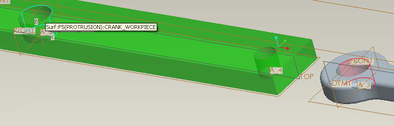
Pro/E will make assumptions as to the type of constraint desired. For example, if you select a circular feature on both parts, pro/E will default to assuming you want them to be concentric. If this is not what you want, we can change it later. Start by selecting the top face of your wrench by mousing over it and clicking when it is highlighted as shown below.Now click on the workpiece's top surface and then the pedal crank's surface.
Next, click on the top surface of the workpiece. This will align the top surfaces of both parts. The Component Placement window will change to show that one connection has been made.
Next, select one of the inside surfaces of the larger hole in your crank as shown below. it will turn red when selected.
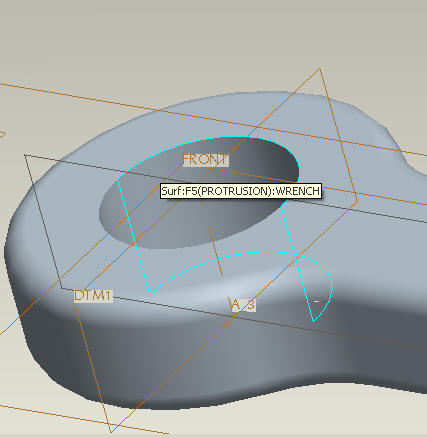
Once it has turned red, select the same side of the surface on the large hole in the workpiece.
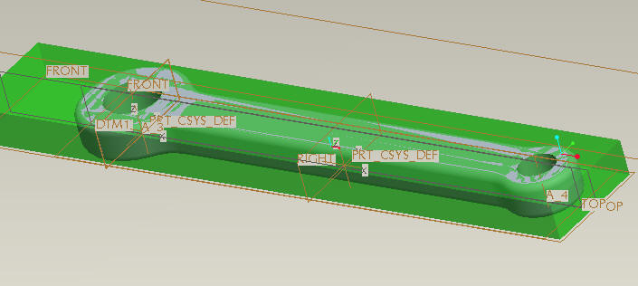
This will move your wrench to be completely enclosed inside the workpiece.
On the Placement Status window in the bottom of this Component Placement window, you can see the change in status from "Not Fully Constrained" to "Fully Constrained", as shown below.
Click the OK button. This completes placement of your model into the machining environment, so click Done/Return in the Menu Manager as shown below.
The next step will be to create the machining paths that will actually cut your model out from the blank. Select Machining from menu manager.
We will be creating an NC sequence, so select NC Sequence from menu manager as shown below
The operation we will be doing is called Profile Milling. Profile milling uses the side of the tool to cut the outside of a workpiece to shape. Select Profile from Menu Manager.
With Profile selected, click Done.
Now we will set up the sequence in which the cut's path will be. The first and second passes will be roughcuts. And the third and forth will be our finalcuts. For our first machining pass, specify Name, Tool, Parameters and Surfaces. Check those boxes in Menu Manager as shown below, then click Done.
When you click Done, you will be prompted to enter the name for this operation at the bottom of the main screen. Enter Rough_pass_1 and click the green arrow at the right as shown below.
![]()
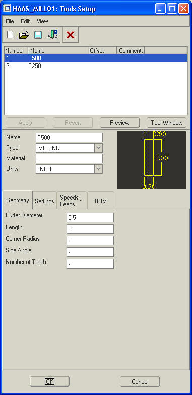
The machining enviroment has already been set up with the two tools you will
be using. There are two toolparts loaded in this .mfg file, you do not need
to add any other .tpm file. Click onT500 (a half inch mill)
because it is the larger tool and we will use it for the roughcut. Then click
OK.
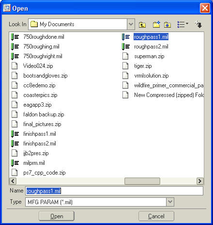
Now we must specify the program what parameters to machine with. These have been provided in the zipped file. For example, they are roughpass1.mil, roughpass2.mil, finishpass1.mil and finishpass2.mil.
Click Retrieve in Menu Manager as shown below
Load roughpass1.mil as shown below by highlighting it and clicking Open.
When you have done that, click Done in Menu manager as shown below.
Now we must select the surfaces to be machined. we will be selecting these from the model, which is the default, so click Done in menu manager as shown below.
From the main window, select the first of
the surfaces to be machined. Next, hold down the Ctrl key and select the rest
of the surfaces. You can also right click on some surfaces, and select Pick
From the List to select which surface you want.
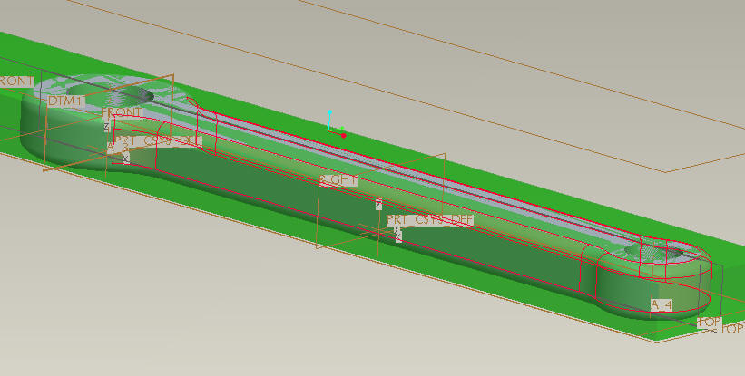
IMPORTANT: Do not select surfaces which are beyond vertical. For example, in
the model shown below, there is a radius on the top and bottom of the part.
Do not select the bottom radius, we will deal with this in the second machining
pass. Do not select the main loop of the side which will be attaching. When
your model looks somewhat like the picture belw, click OK in the small Select
popup.
Click Done in Menu Manager, then Done/Return
To ensure your operation looks like what is expected, we will play it on the screen. Click Play Path in Menu Manager, then click Screen Play.
Pro/E will compute the cutter paths, then display the Play Path window slown below.
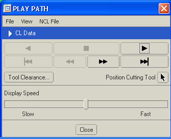
Click the play arrow. Watch the cutter to ensure that it does what you expect. a correct path looks like the following.
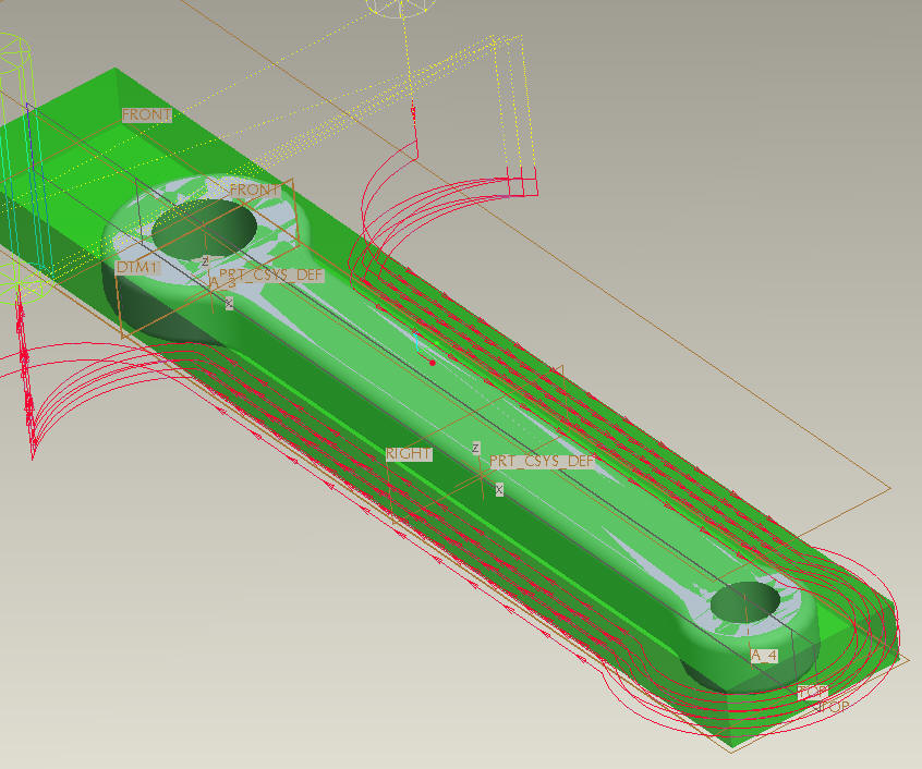
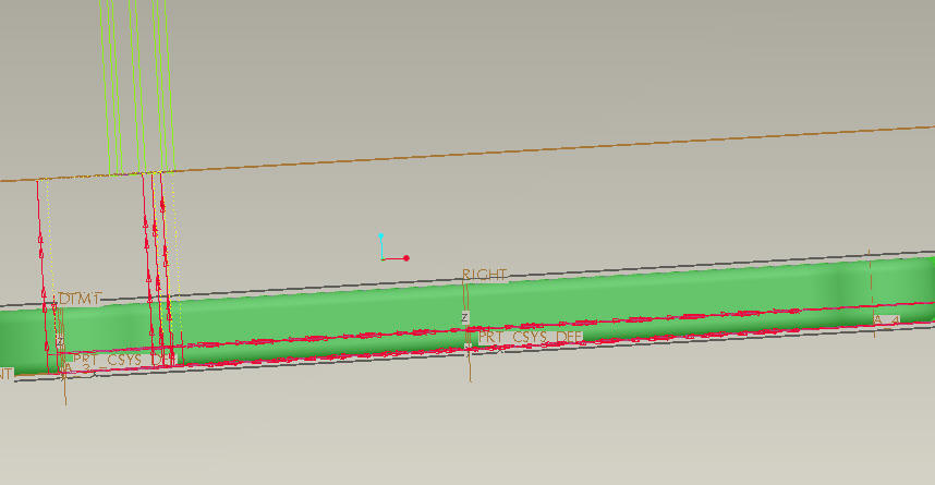
The cutterhead will make either four or eight passes. It is important to make sure that the cutter does not try to cut where the fixturing bolts will be. If you rotate the view to the front, you will notice that the cutter does not cut all the way to the bottom unless your model has square edges. In the next operation will will compensate for this.
Now, we will create an operation that is
identical to the first, but shifted down by the amount of offset needed to completely
cut out the part. Click Done Seq in menu manager, then Done/Return.
Next, click on Machining, then NC Sequence, then New
Sequence as shown below
Again, select Profile and click Done
Now, select Name, Parameters and Surfaces. Because we will be using the same tool as the last operation again, we do not need to re-select it. When you have these three selected, click Done.
Name this pass Rough_pass_2, then click the green arrow
![]()
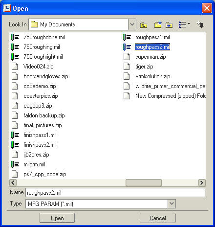
When the MRG PARAMS section of menu manager comes up, click Retrieve, then load roughpass2.mil
Now we must set the amount of offset for your particular model. Click Set in Menu manager.
This will bring up the Param Tree window. The setting we need to change is an Advanced option, so click Advanced.
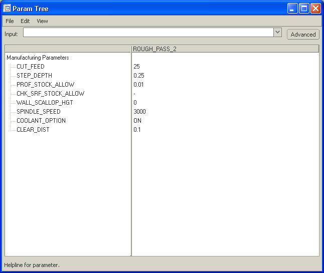
When you click on Advanced, more options will appear. the setting we want is called Axis_Shift
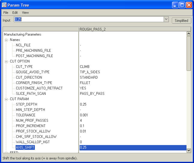
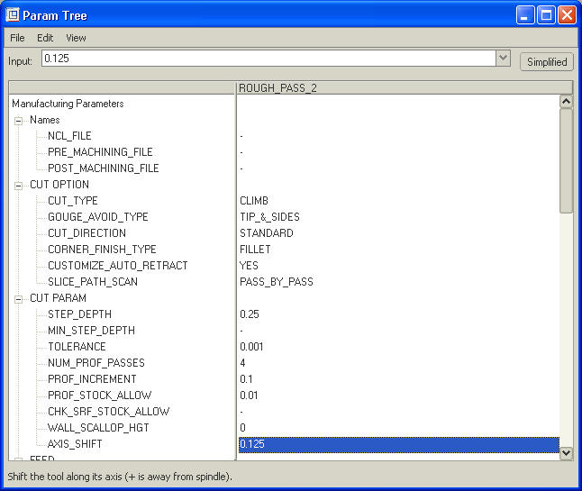
Select this property, then type in the amount
of offset that will bring the cutterhead right to the edge of your part. For
example, if your crank has an eigth inch round on both edges, type in .125.
If your crank's edge is completely rounded such that the widest part is only
exactly in the center, type in .25.
Warning: it is critical that you get this value exactly
right to prevent the cutter from possibly contacting the (very expensive) CNC
machine, or not cutting out your part completely.
When you have typed in the correct value, press Enter and it will be
updated.
When you have the correct value for Axis Shift, click on File, then Exit as shown below.
Now, click Done in menu manager.
Then we must again tell the machine what surfaces to use. Fortunately, we are machining the same surfaces, only shifted, so click From Prev Seq under NCSEQ SURFS, then select Rough_Pass_1, as shown below. When you have checked it, click Done Sel.
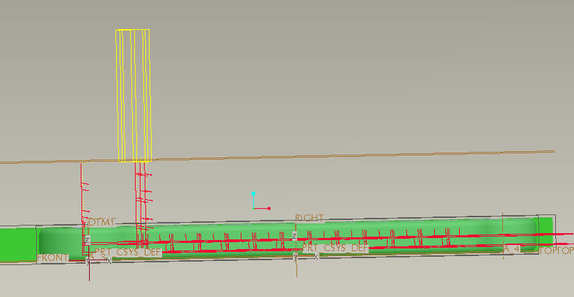
Next, click Done/Return, then play the path like we did in the previous step. When the playing is finished, rotate the view to the front and make sure that the lowermost red cut line lines up exactly with the bottom of the workpiece. If it does, you may proceed with the tutorial by selecting Done Seq. If it does not, then click Quit Seq, then click Confirm and re-do the second machining operation. Only proceed to the next step if your front view looks like the following
Now we will be doing a finishing pass with a smaller cutter at higher speed. Create another NC sequence by selecting NC sequence, New Sequence, Profile, Done. On the Seq Setup screen, check the Name, Tool, Parameters and Surfaces boxes, then click Done. Name this sequence Finish_pass_1 and click the green arrow. Tools setup will appear.

Select T250, then click OK.
Under MFG Params, click Retrieve and load finishpass1.mil, then click Done.
When NCSEQ Surfs appears, select From Prev Seq again, then select Rough_Pass_1 and click Done Sel. and then Done/Return.
Click Play path, then screen play. When you're confident that the path is correct (roughly like shown below), close the Play Path window and click Done Seq and Done/Return.
Next step is to create an axis-shifted version of the finish cut which is exactly like you did with the rough passes. Retrieve finishpath2, then again set your axis shift to the correct amount. Use previous sequence to select your surfaces. When you play the path, it should look like below.
When all 4 of your operations are correct, then its time to create the file that will be used to cut the crank on the CNC mill. Select CL Data from the Machining section of Menu manager as shown below.
Menu Manager will change to asking for the feature you wish to process. Click on OP010 in left side of the main window as shown below.
Menu Manager will now change. Select File, then from the options
at the bottom select CL File, Interactive
and Compute CL as shown below. With these selected, click Done.
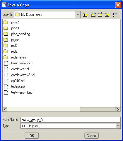
You will be prompted to specify a file name for your part. Enter in crank_group_X where X is your group number as shown below, then click OK.
When the bottom status window of the main screen shows
![]()
Then you are finished. Click Done Output in Menu Manager, then Done/Return until you get back to the main Manufacture menu. At this time, save your work in case you need to modify or fix it in the future. Send the .ncl file you created to Jim Dillinger (jimd(at)cmu.edu) to be post-processed and run.